Communication terminal apparatus and antenna device
- Summary
- Abstract
- Description
- Claims
- Application Information
AI Technical Summary
Benefits of technology
Problems solved by technology
Method used
Image
Examples
first preferred embodiment
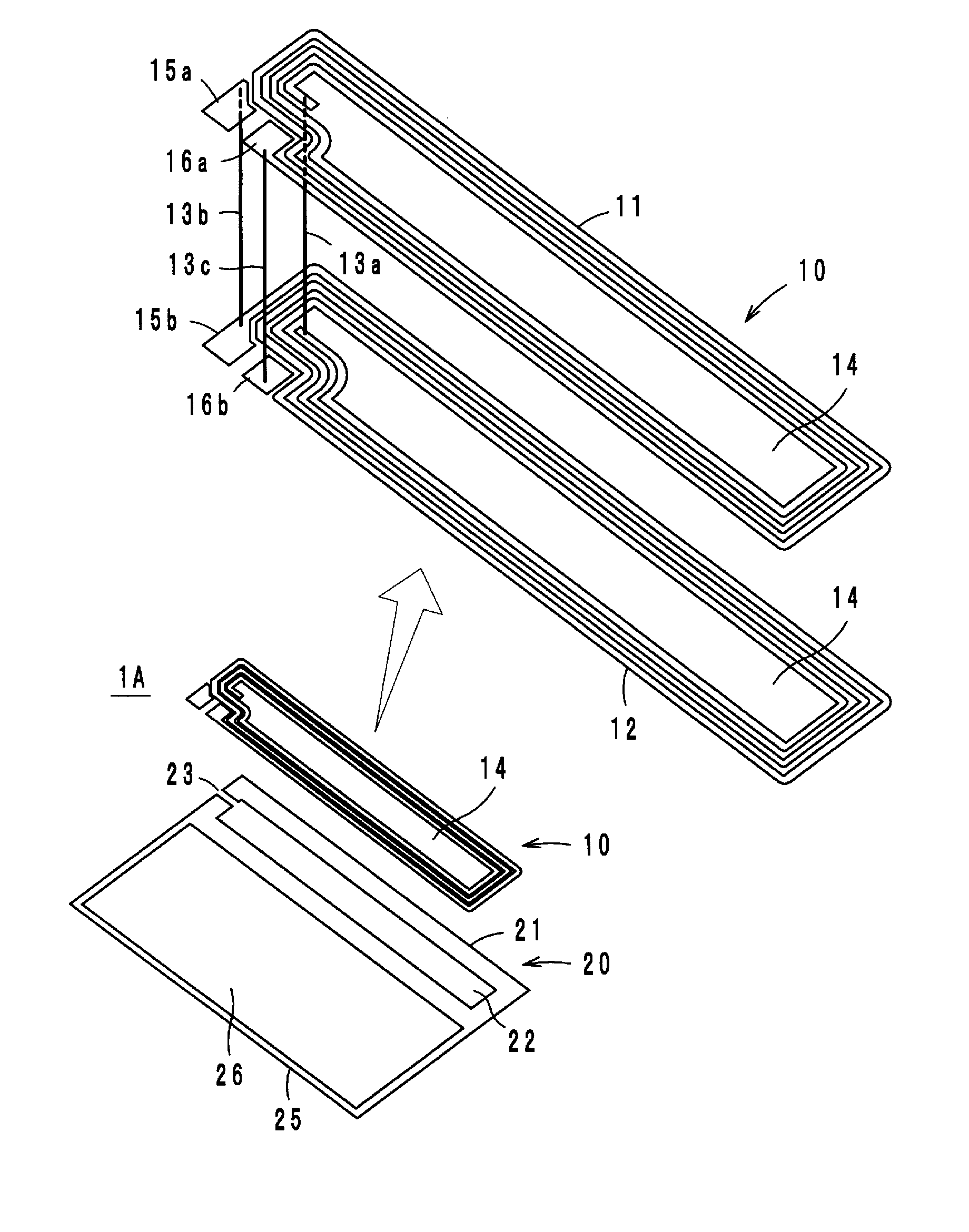
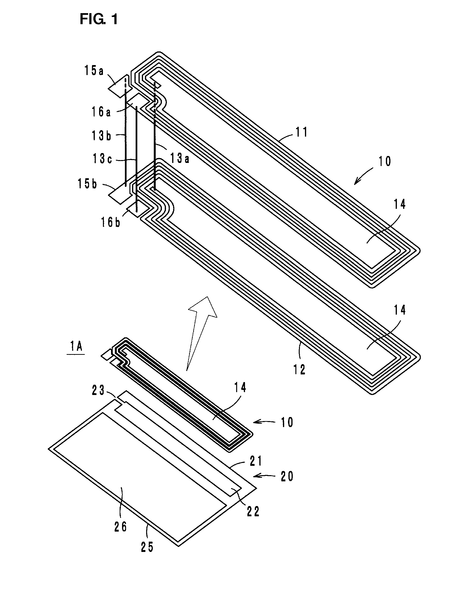
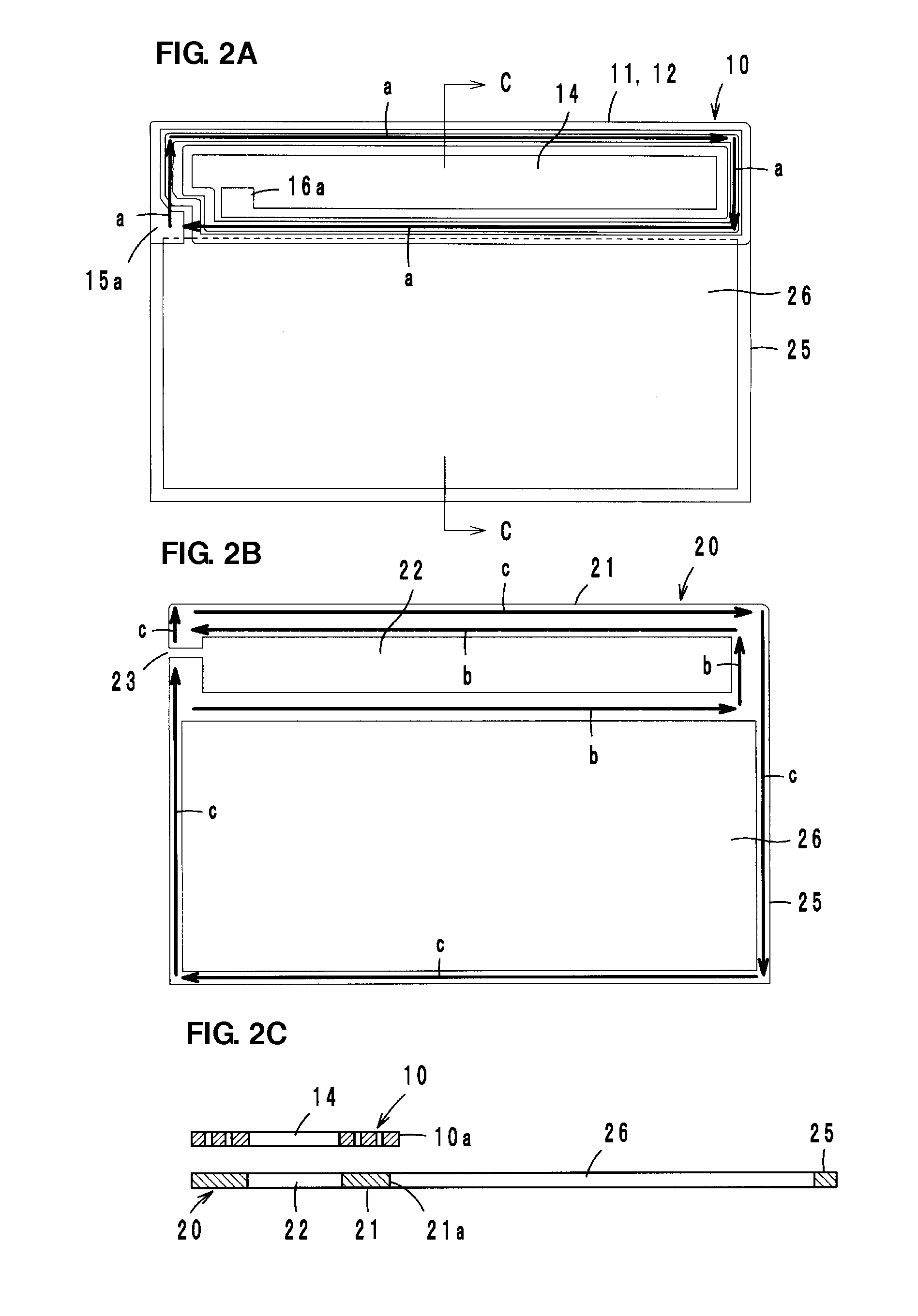
[0028]Referring to FIG. 1, an antenna device 1A according to a first preferred embodiment of the present invention includes a coil conductor 10 and a booster conductor 20. The coil conductor 10 preferably has a two-layer stacked structure including an insulating sheet, which is not illustrated in the figure, between the layers, for example. Loop-shaped conductors 11 and 12 that are wound so as to be superposed with each other in plan view are connected at ends thereof through a via hole conductor 13a, thereby forming a single coil including a first opening 14 at the center of the winding. Further, feeding terminals 15a and 15b are connected to each other through a via hole conductor 13b, and feeding terminals 16a and 16b are connected to each other through a via hole conductor 13c. The feeding terminal 15b is connected to one end of the loop-shaped conductor 12 and the feeding terminal 16a is connected to one end of the loop-shaped conductor 11. The feeding terminals 15a and 16a are...
second preferred embodiment
[0042]Referring to FIGS. 9A and 9B, an antenna device 1B according to a second preferred embodiment of the present invention preferably includes a frame-shaped radiation conductor portion 25 that is connected to two points located on a diagonal line of a square-shaped coupling conductor portion 21. A coil conductor 10 is overlaid on the coupling conductor portion 21 as a single-layer loop-shaped conductor 18 that is preferably wound in a square shape, for example. The two ends of the loop-shaped conductor 18 define feeding terminals 18a and 18b. The antenna device 1B has the same or substantially the same operations and advantages as the antenna device 1A.
third preferred embodiment
[0043]Referring to FIGS. 10A and 10B, an antenna device 1C according to a third preferred embodiment of the present invention preferably includes a coil conductor 10 and a coupling conductor portion 21 that are substantially L-shaped, for example, and are superposed with each other. The coil conductor 10 is defined by a single-layer loop-shaped conductor 18, and the two ends of the loop-shaped conductor 18 define feeding terminals 18a and 18b. The antenna device 1C also has the same or substantially the same operations and advantages as the antenna device 1A.
PUM
 Abstract
Description
Claims
Application Information
 - R&D
- Intellectual Property
- Life Sciences
- Materials
- Tech Scout
- Unparalleled Data Quality
- Higher Quality Content
- 60% Fewer Hallucinations
Browse by: Latest US Patents, China's latest patents, Technical Efficacy Thesaurus, Application Domain, Technology Topic, Popular Technical Reports.
© 2025 PatSnap. All rights reserved.Legal|Privacy policy|Modern Slavery Act Transparency Statement|Sitemap|About US| Contact US: help@patsnap.com


