Flat Panel Display Device, Stereoscopic Display Device, and Liquid Crystal Display Device

a display device and liquid crystal technology, applied in the field of display techniques, can solve the problems of high material cost, high cost complex structure, etc., and achieve the effect of reducing the expenditure of back frame mold, saving material for back frame, and simple mold structur

Inactive Publication Date: 2013-05-23
TCL CHINA STAR OPTOELECTRONICS TECH CO LTD
View PDF4 Cites 1 Cited by
  • Summary
  • Abstract
  • Description
  • Claims
  • Application Information

AI Technical Summary

Benefits of technology

[0018]The efficacy of the present invention is that to be distinguished from the state of the art, the present invention provides a flat panel display device, a stereoscopic display device, and a liquid crystal display device that form a back frame through joining assembling pieces so that the structure of a mold for back frame is simple, the expenditure for the back frame mold is reduced, the material for the back frame is saved, and the cost is lowered down. Further, through the pawl mating arrangement of the bracing piece and the assembling piece, the bracing piece of the back frame realizes fast mounting and removal.

Problems solved by technology

The unitary back frame 10 consumes much material and has a high material cost.
Further, a large-sized back frame 10 requires large-sized stamping equipment, and the size of mold corresponding to such a back frame 10 is large and the structure complicated, making the expenditure of the back frame mold high.
As a consequence, the conventional back frame is of a high cost.

Method used


Image

  • Flat Panel Display Device, Stereoscopic Display Device, and Liquid Crystal Display Device
  • Flat Panel Display Device, Stereoscopic Display Device, and Liquid Crystal Display Device
  • Flat Panel Display Device, Stereoscopic Display Device, and Liquid Crystal Display Device

Examples


first embodiment

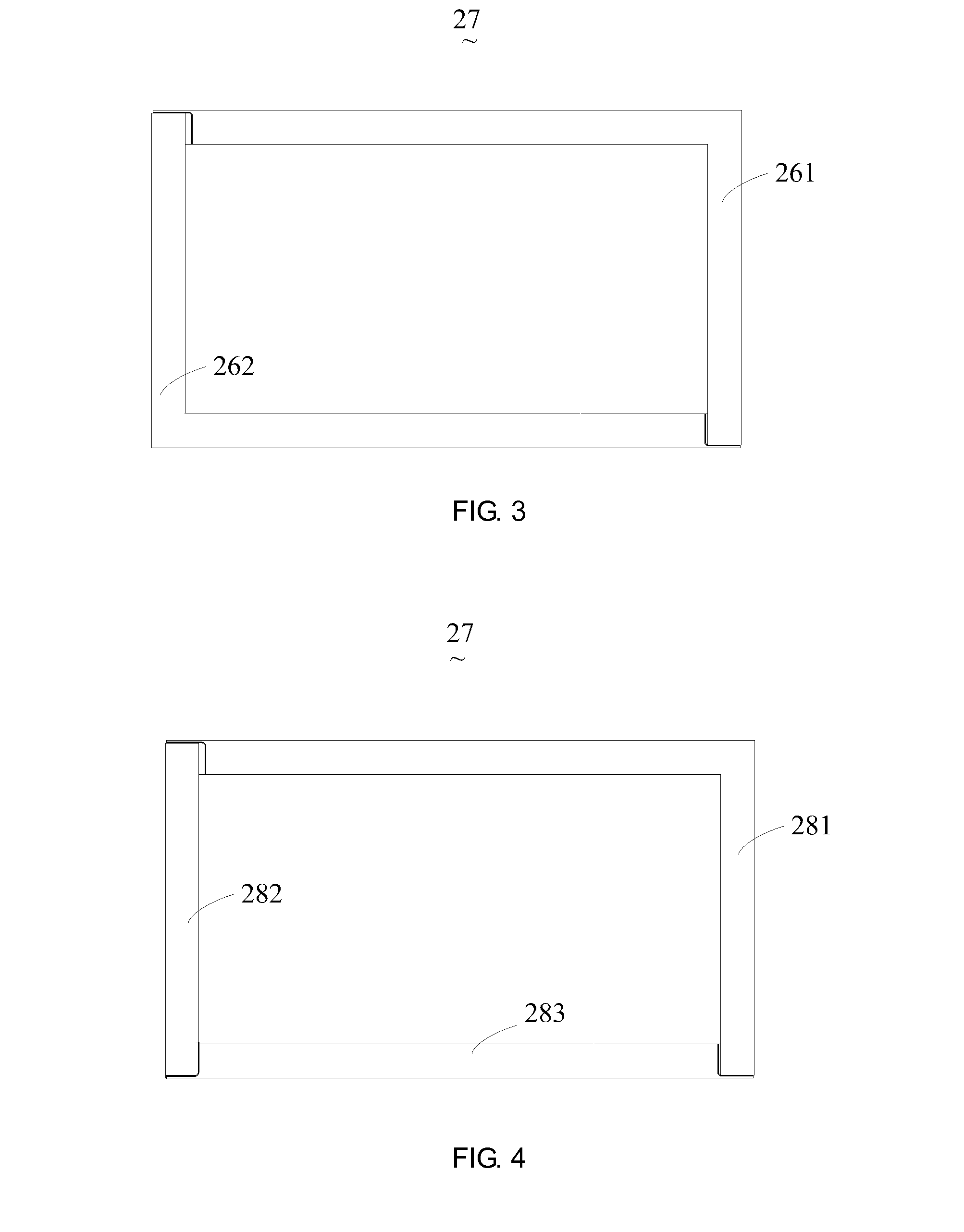
[0042]Referring also to FIG. 3, the back frame 23 of the first embodiment comprises a first primary assembling piece 261 and a second primary assembling piece 262. The first primary assembling piece 261 has an end joined to an end of the second primary assembling piece 262, and the first primary assembling piece 261 has another end joined to another end of the second primary assembling piece 262 in order to form the main frame structure 27 of the back frame 23. The first primary assembling piece 261 and the second primary assembling piece 262 are both aluminum pieces or galvanized steel pieces. In the instant embodiment, the first primary assembling piece 261 and the second primary assembling piece 262 are L-shaped.

second embodiment

[0043]Referring also to FIG. 4, the back frame 23 of a second embodiment comprises a first primary assembling piece 281, a second primary assembling piece 282, and a third primary assembling piece 283. The three primary assembling pieces 281, 282, and 283 are assembled and joined to form a main frame structure 27 of the back frame 23. The three primary assembling pieces 281, 282, and 283 are all aluminum pieces or galvanized steel pieces. In the instant embodiment, the first primary assembling piece 281 is L-shaped, and the second and third primary assembling pieces 282, 283 are straight linear.

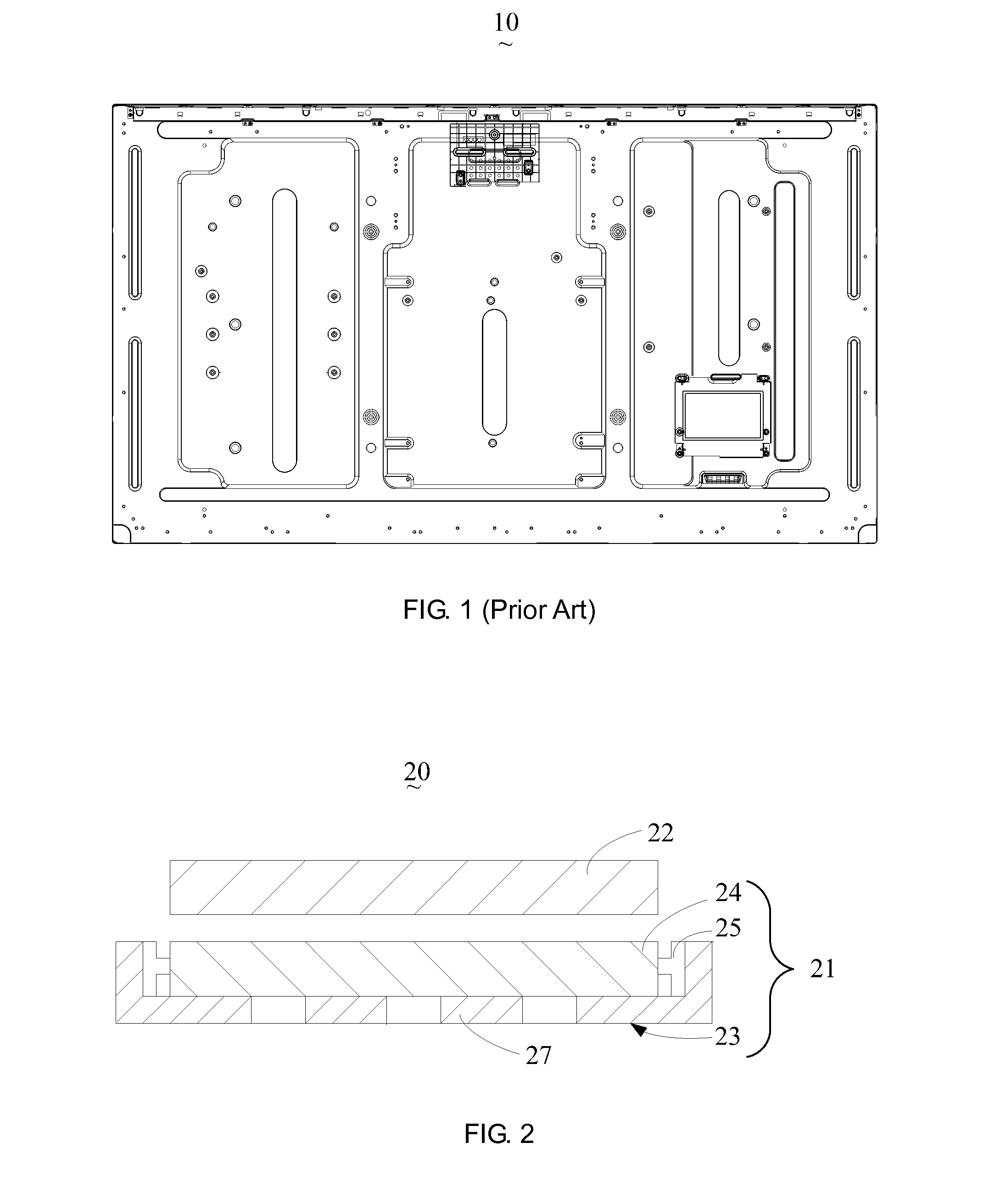
[0044]Further, the back frame 23 further comprises secondary assembling pieces arranged inside and joined to the main frame structure 27.

[0045]A detailed description will be given to the back frame 23 of the flat panel display device 20 according to the present invention, which comprises four primary assembling pieces and two secondary assembling pieces.

fourth embodiment

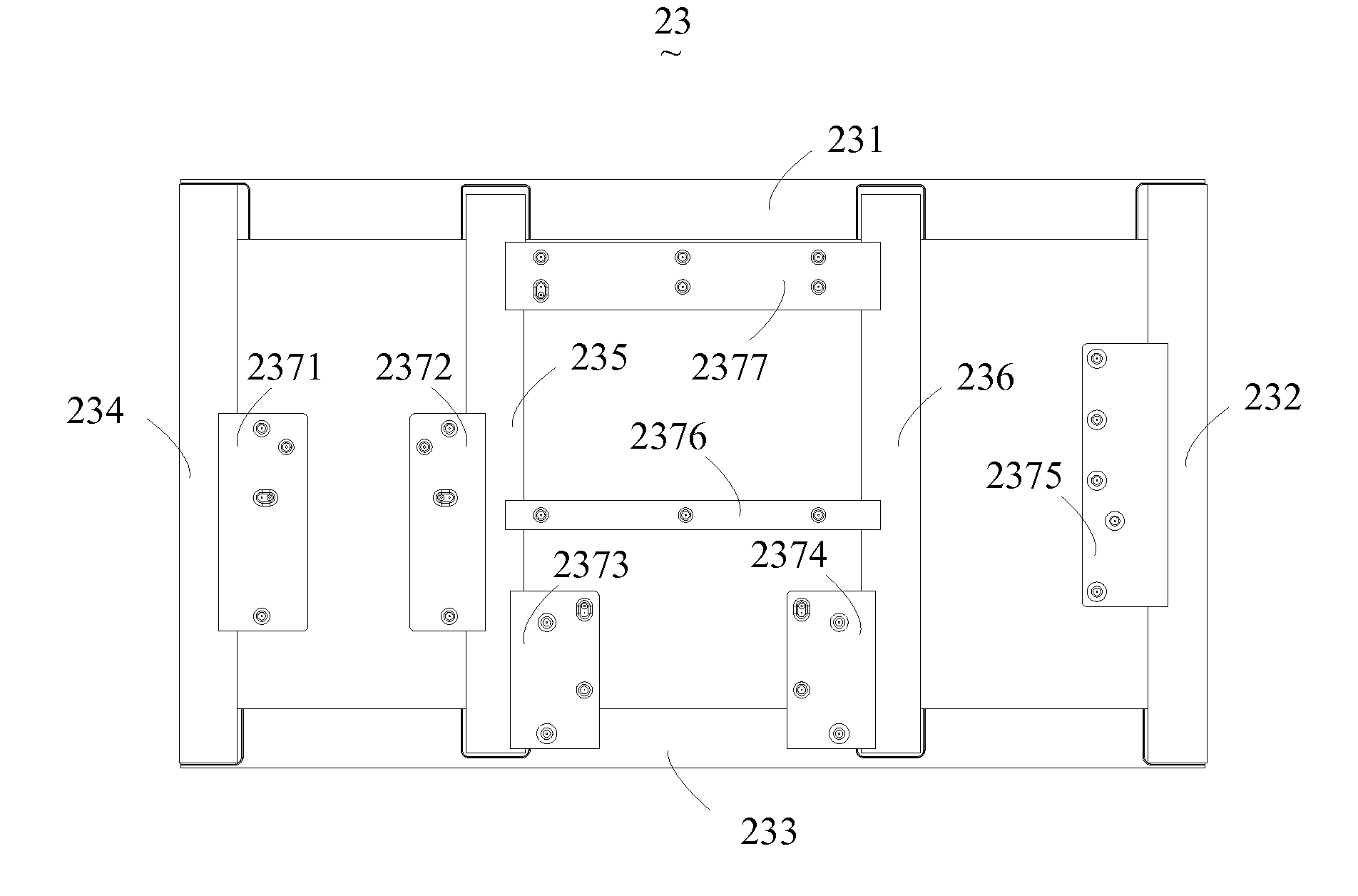
[0046]Referring to FIG. 5, FIG. 5 is a schematic view showing a back frame of flat panel display device according to the present invention. As shown in FIG. 5, in the instant embodiment, a back frame 23 comprises: a first primary assembling piece 231, a second primary assembling piece 232, a third primary assembling piece 233, a fourth primary assembling piece 234, a first secondary assembling piece 235, a second secondary assembling piece 236, and bracing pieces 2371, 2372, 2373, 2374, 2375, 2376, and 2377. The first primary assembling piece 231, the second primary assembling piece 232, the third primary assembling piece 233, and the fourth primary assembling piece 234 are successively joined to each other in an end-to-end manner to constitute a rectangular main frame structure 27 of the back frame 23. The first secondary assembling piece 235 and the second secondary assembling piece 236, serving as ancillary assembling pieces, are arranged in the main frame structure 27 and joined...


PUM

PropertyMeasurementUnit
sizesaaaaaaaaaa
sizesaaaaaaaaaa
sizesaaaaaaaaaa

Abstract

The present invention provides a flat panel display device, a stereoscopic display device, and a liquid crystal display device. The flat panel display device includes a backlight system and a display panel, wherein the backlight system includes a light source, a light homogenization mechanism, and a back frame; the back frame carries the light source and the light homogenization mechanism and the back frame includes at least two assembling pieces. The at least two assembling pieces are joined to form the back frame. The back frame further includes a bracing piece that is set in pawl mating engagement with the assembling pieces. The present invention forms a back frame through joining assembling pieces so that the structure of a mold for back frame is simple, the expenditure for the back frame mold is reduced, the material for the back frame is saved, and the cost is lowered down. Further, through the pawl mating arrangement of the bracing piece and the assembling piece, the bracing piece of the back frame realizes fast mounting and removal.

Description

BACKGROUND OF THE INVENTION[0001]1. Field of the Invention[0002]The present invention relates to the field of displaying techniques, and in particular to a flat panel display device, a stereoscopic display device, and a liquid crystal display device.[0003]2. The Related Arts[0004]The state-of-the-art liquid crystal display device comprises a front bezel, a panel, and a backlight module, of which the backlight module comprises a back frame, a reflector plate, a light guide, and a lighting assembly.[0005]Currently, a variety of display panels of different sizes are available in the market to meet different needs of general consumers. For example, in the field of television set, the sizes of liquid crystal panels include 31.5, 42, 46, 48, and 55 inches. Different back frame molds are provided for liquid crystal planes of different sizes.[0006]Referring to FIG. 1, FIG. 1 is a schematic view showing a conventional back frame of liquid crystal display device. As shown in FIG. 1, the conve...

Claims


Application Information

Patent Timeline
Patent Type & Authority Applications(United States)
IPC IPC(8): G02F1/13357G09F13/04H04N13/30
CPCG02F2001/133314G02F2201/465H04N13/04H04N13/0404G02B6/009G02F2001/133325G02F2001/133328G02F2201/46G02B6/0088G02F1/133308H04N13/305H04N13/30G02F1/133328G02F1/133325G02F1/133314
Inventor QUE, CHENG-WENHSIAO, YU-CHUNKUO, YI-CHENG
Owner TCL CHINA STAR OPTOELECTRONICS TECH CO LTD
Why Eureka
Try Eureka