Anti-rotation mounting mechanism for a round insert

a mounting mechanism and insert technology, applied in the field of anti-rotation mounting mechanisms for inserts, can solve the problems of affecting the quality of the cut on the workpiece, affecting the quality of the cut, so as to prevent the removal of a weakening amount of material, avoid localized point-type stresses, and equalize stresses

Active Publication Date: 2013-05-23
KENNAMETAL INC
View PDF10 Cites 16 Cited by
  • Summary
  • Abstract
  • Description
  • Claims
  • Application Information

AI Technical Summary

Benefits of technology

[0011]In order to prevent the removal of a weakening amount of material from the insert, the rounded stop surfaces are tapered relative to the side surfaces of the insert; i.e., the stop surfaces increase in depth between the upper and lower surfaces of the insert such that sidewalls of the insert appears to be scalloped in a continuous sinusoidal pattern. Additionally, in order to equalize stresses between the insert walls and pocket walls, the pocket preferably includes two anti-rotation surfaces for simultaneously engaging two of the rounded stop surfaces of the insert. Finally, the anti-rotation surface is preferably located on a lower portion of the pocket sidewalls, and the upper portion of these sidewalls engages an upper portion of the insert sidewall to provide the primary support between the insert and the pocket.
[0012]The obliquely oriented, inter-fitting surfaces defined by the partial radius curves around the insert sidewalls and the sidewalls of the pocket provide an interference joint characterized by either a broad line-type or lenticular-surface type contact between the insert and the pocket in the tool body, avoiding localized point-type stresses which could either chip or crack the insert body or create wear patterns in the walls of the insert-receiving pocket. The contact between the upper sidewalls of the pocket and the insert substantially insulates the interference joint created by the stop and anti-rotation surfaces from the load applied between the insert and the pocket as a result of a cutting operation.

Problems solved by technology

During a cutting operation, such inserts often experience not only compressive and vibratory forces, but some amount of torque due to the angle between the cutting edges of the inserts and the workpiece.
If the clamping screw should become sufficiently loosened, it can vibrate within the surrounding pocket severely enough to become chipped or cracked not only ruining the insert, but also jeopardizing the quality of the cut on the workpiece.
Unfortunately, a number of shortcomings associated with each design have been noticed.
Additionally, the provision of such deep recesses around the bottom of the insert body result in an undesirable weakening of the insert body as a result of the removal of the material necessary to form the recesses.
However, the limited contact provided by such a design can result in one-point contact between the edges of the insert facets and the flat walls of the pocket.
Hence the limited and sometimes one-point contact between the insert and the pocket can result in localized chipping, cracking, or breakage of the insert over time.
Unfortunately, this increased distance allows more rotational movement (i.e., clocking) of the cutting insert 103.

Method used


Image

  • Anti-rotation mounting mechanism for a round insert
  • Anti-rotation mounting mechanism for a round insert
  • Anti-rotation mounting mechanism for a round insert

Examples


Embodiment Construction

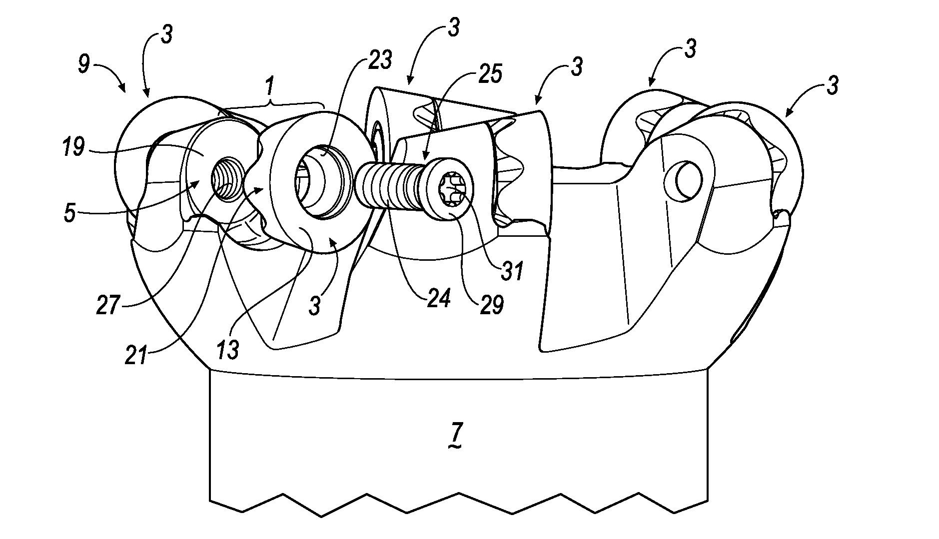
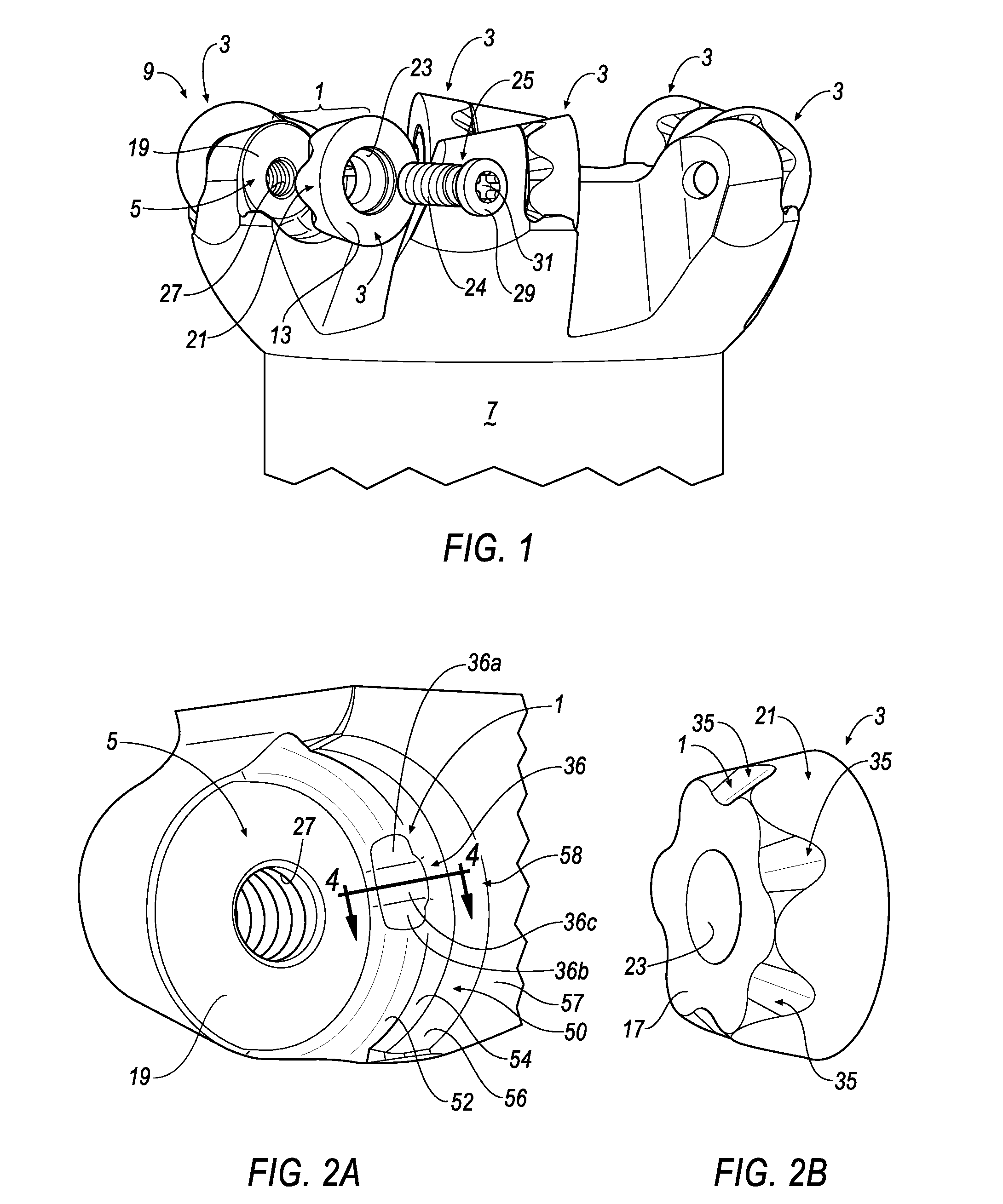
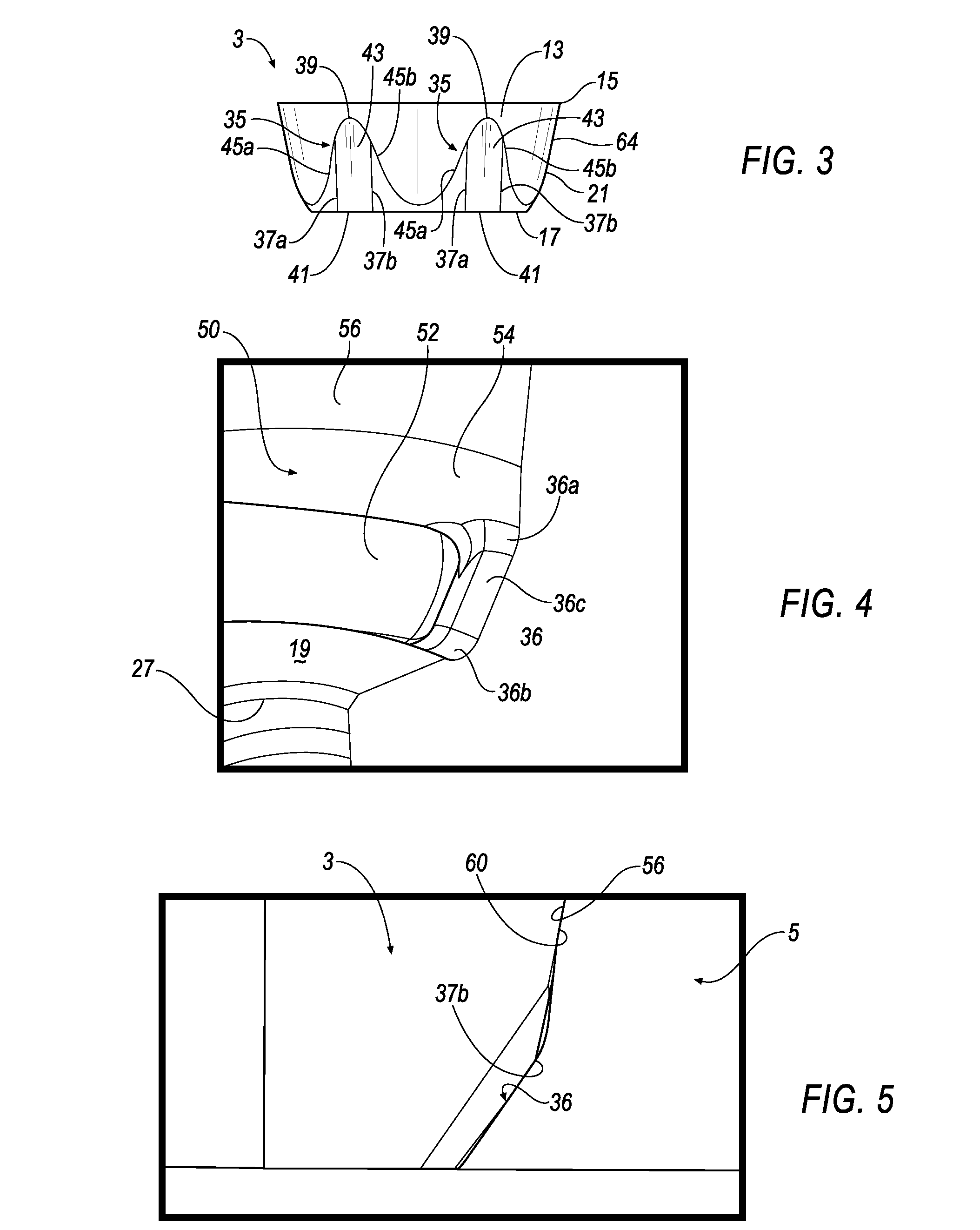
[0026]With reference now to FIGS. 1, 2, and 3, wherein like numerals designate like components throughout all of the several Figures, the anti-rotation mounting mechanism 1 of the invention serves to prevent a round insert 3 from rotating within a pocket 5 present in the body 7 of a milling cutter 9 or other cutting tool. The insert 3 has an upper surface 13 that terminates in a circular cutting edge 15, and a bottom surface 17 that engages the floor 19 of the pocket 5 when the insert 3 is mounted onto the body 7 of the cutter 9. The insert 3 further has a frustro-conical sidewall 21 interconnecting the upper surface 13 and bottom surface 17. A screw hole 23 is centrally disposed through the body of the insert 3 for receiving the threaded shank of a clamping screw 25. The threaded shank 24 is screwed into a threaded bore 27 centrally located in the floor 19 of the pocket 5 in order to secure the insert 3 onto the body 7 of the milling cutter 9. To this end, the clamping screw 25 inc...


PUM

PropertyMeasurementUnit
angleaaaaaaaaaa
angleaaaaaaaaaa
angleaaaaaaaaaa

Abstract

An anti-rotation mounting mechanism is provided between an indexable insert and an insert-receiving pocket in the body of a machine tool, such as a milling cutter. The mechanism includes a plurality of curved stop surfaces uniformly disposed around the side surface of the insert, a portion of which is obliquely oriented with respect to the side surface of the insert, and an anti-rotation feature in the pocket of the tool body having a pair of engagement portions that are substantially complementary in shape to that of the stop surfaces for forming an interference joint between the pocket and the insert. The anti-rotation feature further includes a central planar portion that does not engage the stop surfaces. The mechanism effectively prevents rotation between the insert and pocket without the formation of point-type, localized stresses which can chip or break the insert.

Description

BACKGROUND OF THE INVENTION[0001]The invention generally relates to mounting mechanisms for cutting inserts, and is particularly concerned with a mechanism for preventing the rotation of a round cutting insert mounted onto the body of a cutting tool.[0002]The inserts used in tools such as milling cutters are mounted in complementarily-shaped pockets spaced around the periphery of the tool body. The inserts are typically secured within their respective pockets by clamping screws inserted through a hole provided in the center of the insert. During a cutting operation, such inserts often experience not only compressive and vibratory forces, but some amount of torque due to the angle between the cutting edges of the inserts and the workpiece. For cutting inserts of non-round shapes, such torque does not result in the rotation of the insert due to the interference-type fit between the angled sidewalls of such inserts and the complementarily-shaped walls of the pocket that receive them. B...

Claims


Application Information

Patent Timeline
Patent Type & Authority Applications(United States)
IPC IPC(8): B23C5/22
CPCB23C5/2221B23C2200/045B23C2200/167B23C2200/168Y10T407/1924Y10T407/192Y10T407/1908Y10T407/23Y10T407/2272B23C2210/168B23C5/2213
Inventor HOFFER, BRAD DANIEL
Owner KENNAMETAL INC
Why Eureka
Try Eureka