
Separating machine and method

a technology of separating machine and belt, which is applied in the direction of screening, food preparation, and screening, can solve the problems of reducing the strength of the belt, affecting and affecting the quality of the product, so as to achieve uniform and uniform separation and prolong the service life of the machin

Active Publication Date: 2013-05-23
MODERNPACK HOPPE
View PDF13 Cites 14 Cited by
  • Summary
  • Abstract
  • Description
  • Claims
  • Application Information

AI Technical Summary

Benefits of technology

The present invention provides a separating machine that has a longer service life for the machine and the pressing element, leading to a more uniform implementation of the separating process. The machine has a cooling device for cooling the pressing device, particularly the pressing element, which results in more uniform operation of the separating machine. The cooling device prevents the belt from bulging out and delays fatigue of the belt, leading to more uniform loading of the components of the separating machine and increased service life. The cooling device also reduces temperature fluctuations in the soft product to be separated, which results in higher hygiene standards. The cooling device leads to a more regular belt movement with reduced belt acceleration and deceleration phenomena.

Problems solved by technology

Fatigue of the belt with a reduction in strength is substantially delayed.
That is, therefore, to be distinguished from a direct feed of a cooled product to be separated, to the separating machine, which would then result in greater difficulty in drawing in the product and passing it through the drum.

Method used


Image

  • Separating machine and method
  • Separating machine and method
  • Separating machine and method

Examples


Embodiment Construction

[0068]Certain terminology is used in the following description for convenience only and is not limiting. The words “right,”“left,”“lower,”“upper” and “top” designate directions in the drawings to which reference is made. Unless specifically set forth herein, the terms “a,”“an” and “the” are not limited to one element, but instead should be read as meaning “at least one.” The terminology includes the words noted above, derivatives thereof and words of similar import.

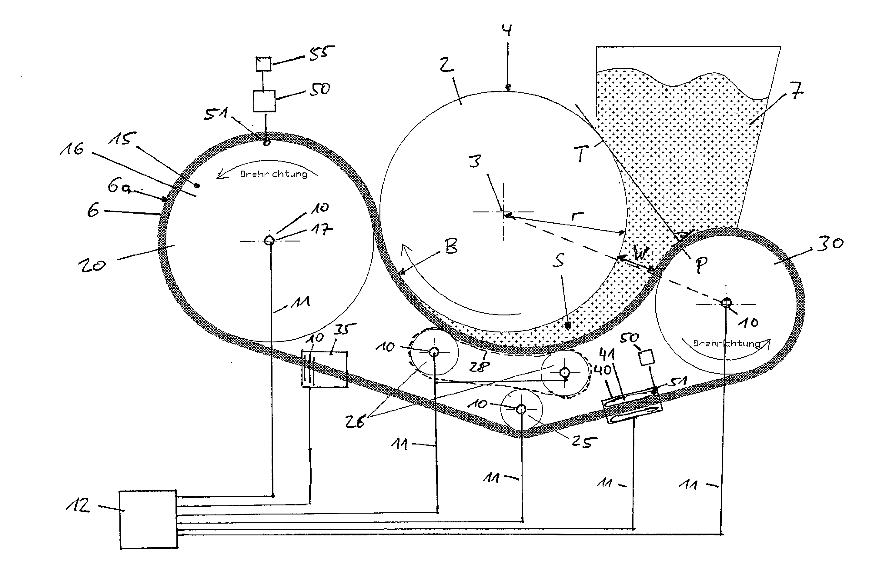
[0069]Referring to the drawings in detail, wherein like numerals indicate like elements throughout the several views, FIG. 1 shows a separating machine 1 according to a preferred embodiment of the present invention for separating products of soft and harder consistency. The separating machine has a drum 2 which is drivable in rotation about an axis 3 and the peripheral surface 4 of which has a plurality of holes, for example in the form of a sieve drum. The hole diameter is here 3 mm. In addition there is a pressing devic...


PUM


Abstract

A separating machine for separating products of soft and harder consistency includes a drum which is drivable in rotation about its axis and the peripheral surface of which has a plurality of holes. A pressing device which by means of a pressing element presses the product to be separated against the peripheral surface of the drum so that product components of soft consistency pass through the drum. A cooling device is provided for cooling the pressing device or the pressing element thereof.

Description

CROSS-REFERENCE TO RELATED APPLICATIONS[0001]This application is a Section 371 of International Application No. PCT / EP2011 / 063359, filed Aug. 3, 2011, which was published in the English language on Feb. 9, 2012, under International Publication No. WO 2012 / 017002 A1 and the disclosure of which is incorporated herein by reference.BACKGROUND OF THE INVENTION[0002]The present invention concerns a separating machine for separating products of soft and harder consistency, including a drum which is drivable in rotation about its axis and the peripheral surface of which has a plurality of holes, and a pressing device which by means of a pressing element presses the product to be separated against the peripheral surface of the drum so that product components of soft consistency pass through the drum.[0003]Separating machines of the general kind set forth are often used, in which the pressing element is in the form of an endless belt which partially extends around the drum so that the product...

Claims


Application Information

Patent Timeline
Patent Type & Authority Applications(United States)
IPC IPC(8): B07B1/24
CPCA22C17/04B07B1/24B30B15/34B30B9/241
Inventor HOPPE, JURGEN
Owner MODERNPACK HOPPE
Learn More