Secondary battery of differential lead structure

a lead structure and secondary battery technology, applied in the field of secondary batteries, can solve the problems of non-uniform resistance between the electrodes, local or partial heat generation or side reactions, and significant heat generation affecting the performance of the secondary battery, and achieve the effect of accelerating the degradation rate of the battery and deteriorating the battery performan

Inactive Publication Date: 2013-05-23
LG CHEM LTD
View PDF1 Cites 3 Cited by
  • Summary
  • Abstract
  • Description
  • Claims
  • Application Information

AI Technical Summary

Benefits of technology

[0018]As a result, a non-uniform resistance between the electrodes even in the same battery may occur, leading to local or partial heat generation or side reactions. The local or partial heat generation may deteriorate the performance of the battery and accelerate the degradation rate of the battery.

Problems solved by technology

Since a high electric current flows particularly between a high-capacity secondary battery and external devices, and the electrode structure, in particular, an electrode lead acts as an interface to electrically connect the high-capacity secondary battery to the external devices, the electrical resistance of the electrode lead may be one cause of heat generation considerably affecting the performance of the secondary battery.
Since heat generation fatally deteriorates the performance of the secondary battery allowing electrochemical reactions as described above, there is an urgent need to solve these problems of the secondary battery confronted in a high electric current atmosphere.
As a result, a non-uniform resistance between the electrodes even in the same battery may occur, leading to local or partial heat generation or side reactions.
The local or partial heat generation may deteriorate the performance of the battery and accelerate the degradation rate of the battery.
However, this may cause a short circuit between electrodes when swelling occurs or external physical impacts are applied.

Method used


Image

  • Secondary battery of differential lead structure
  • Secondary battery of differential lead structure
  • Secondary battery of differential lead structure

Examples


Embodiment Construction

[0038]The present invention will now be described in detail with reference to the accompanying drawings. Prior to description, it should be understood that terms and words used in the specification and the appended claims should not be construed as having common and dictionary meanings, but should be interpreted as having meanings and concepts corresponding to technical ideas of the present invention in view of the principle that the inventor can properly define the concepts of the terms and words in order to describe his / her own invention as best as possible.

[0039]Accordingly, the description proposed herein is just a preferable example for the purpose of illustrations only, not intended to limit the scope of the invention, so it will be apparent to those skilled in the art that various modifications and variation can be made in the present invention without departing from the spirit or scope of the invention.

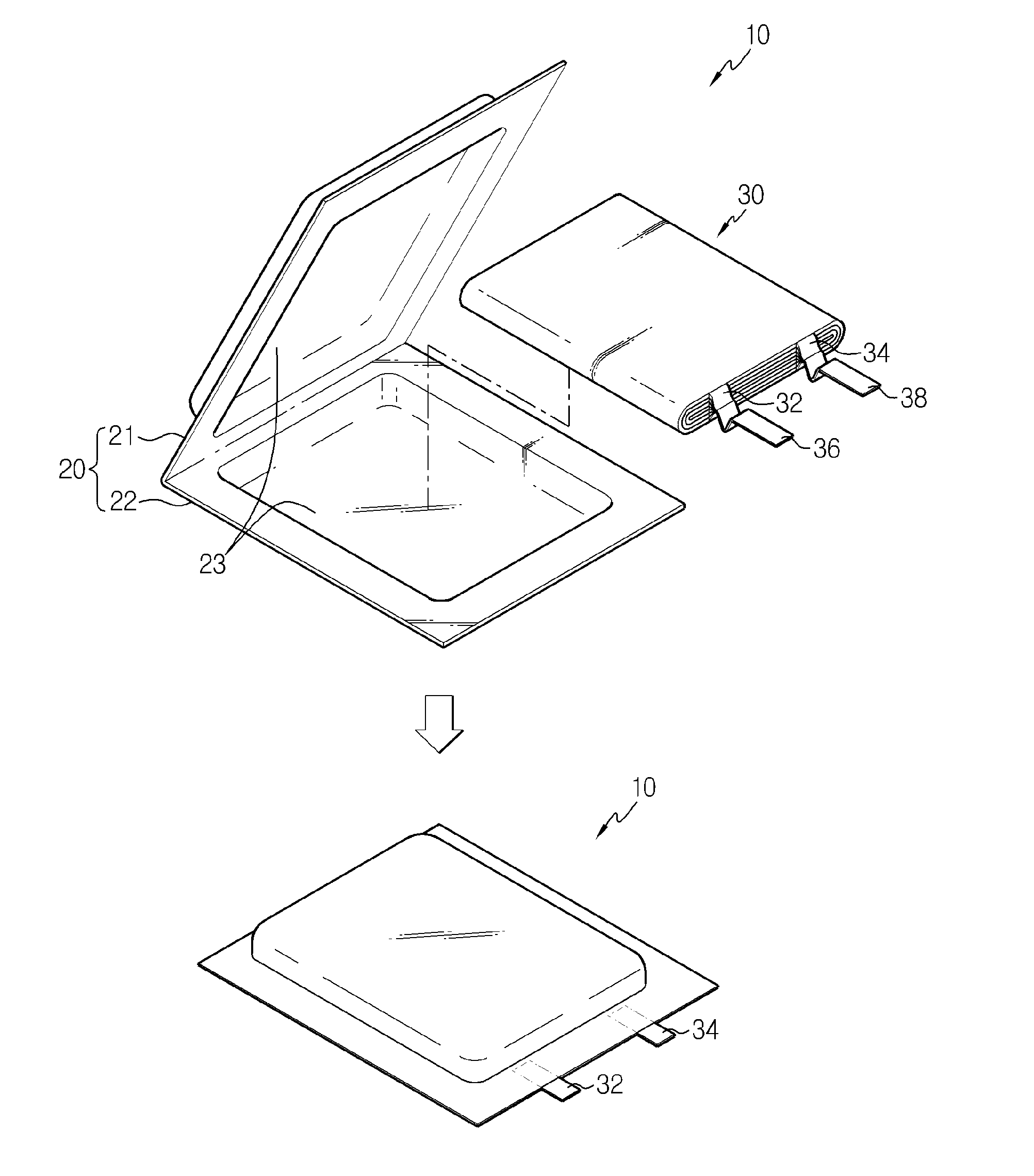
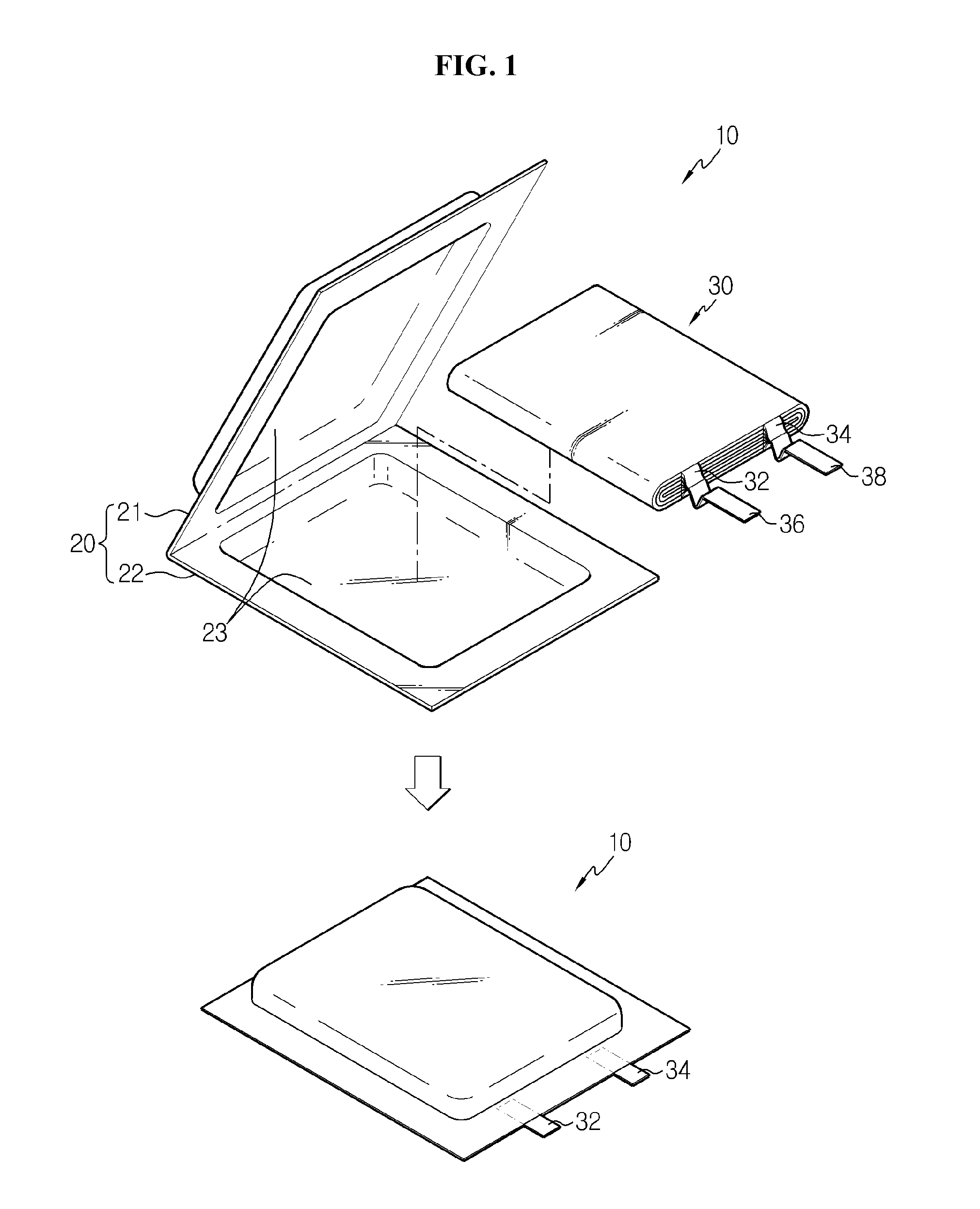
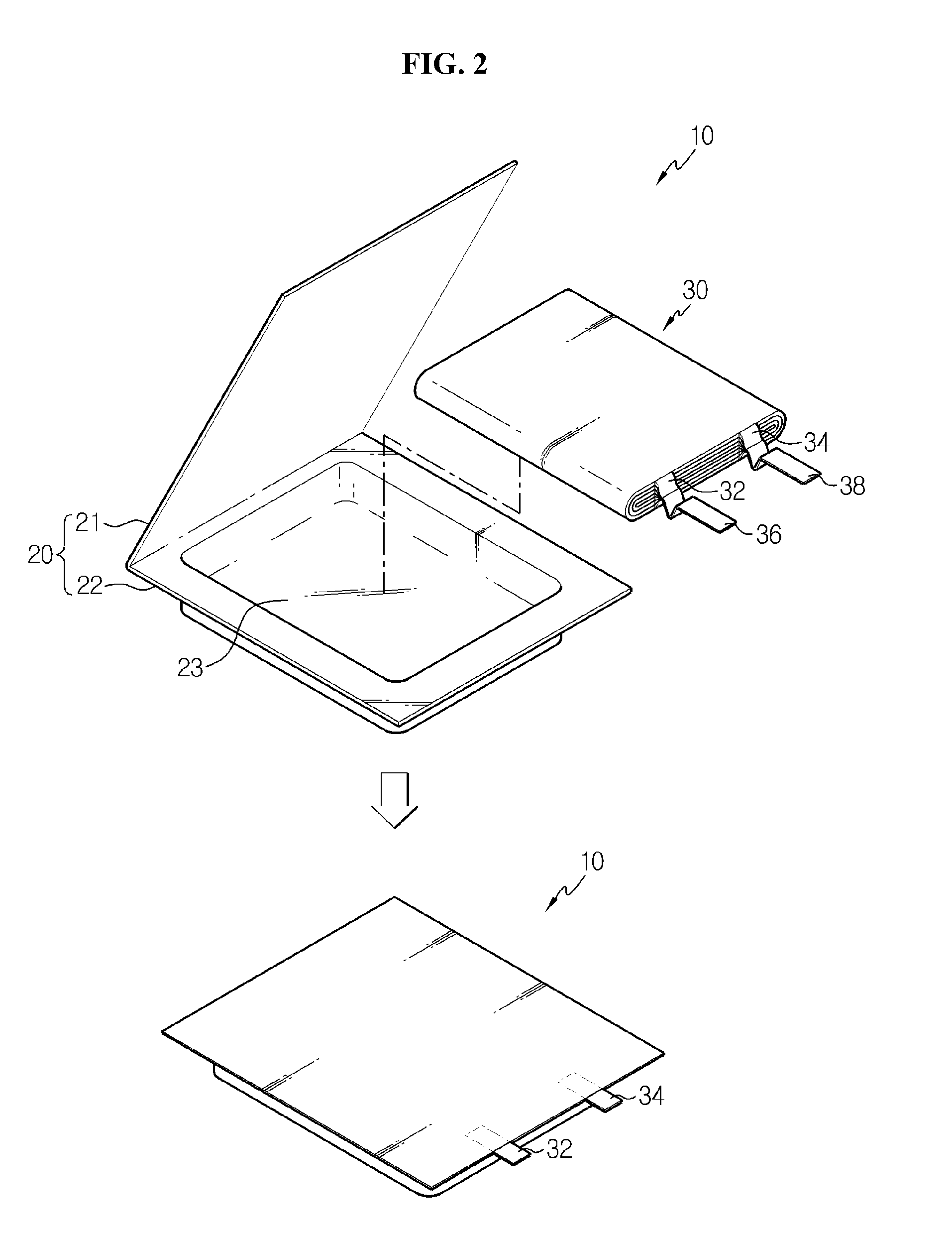
[0040]FIG. 3 is a plane view illustrating each element of a secondary bat...


PUM

PropertyMeasurementUnit
electrical conductivityaaaaaaaaaa
thicknessaaaaaaaaaa
areaaaaaaaaaaa

Abstract

Disclosed is a secondary battery of a differential lead structure including an electrode assembly including a cathode plate having a cathode tab, an anode plate having an anode tab, and a separator interposed between the cathode plate and the anode plate, a battery casing to receive the electrode assembly, a cathode lead electrically connected to the cathode tab, and an anode lead electrically connected to the anode tab and made of a different material from the cathode lead, wherein the cathode lead and the anode lead have a differential cross sectional area such that the lead having lower electrical conductivity has a larger cross sectional area than the other lead having higher electrical conductivity.

Description

CROSS-REFERENCE TO RELATED APPLICATION[0001]This application is a continuation of International Application PCT / KR2011 / 005293 filed on Jul. 19, 2011, which claims priority from Korean Patent Application No. 10-2010-0069499, filed on Jul. 19, 2010, the entire disclosure of which is incorporated herein by reference for all purposes.BACKGROUND[0002]1. Field[0003]The present invention relates to a secondary battery of an improved electrical structure, and more particularly, to a secondary battery having a lead of differential electrical characteristics to improve the electrical characteristics of a high-capacity secondary battery.[0004]2. Description of Related Art[0005]Secondary batteries have high applicability depending on the product group and excellent electrical characteristics such as high energy density, and thus are commonly being used as electric power sources of electric vehicles (EVs) or hybrid vehicles (HVs) as well as mobile devices.[0006]These secondary batteries do not g...

Claims


Application Information

Patent Timeline
Patent Type & Authority Applications(United States)
IPC IPC(8): H01M2/30H01M50/55H01M50/553H01M50/557H01M50/562H01M50/566
CPCH01M2/30H01M2/0212Y02E60/10H01M50/557H01M50/553H01M50/55H01M50/566H01M50/562
Inventor LEE, EUN-JUSHIN, YOUNG-JOON
Owner LG CHEM LTD
Why Eureka
Try Eureka