
Direct methanol fuel cell

a fuel cell and separator technology, applied in the direction of cell components, electrochemical generators, cell component details, etc., can solve the problems of insufficient fuel supply for the catalyst layer, increased power consumption and usage time of these devices, and insufficient practical use of dmfc, so as to reduce the effect of battery performance degradation

Inactive Publication Date: 2006-09-21
PANASONIC CORP
View PDF6 Cites 2 Cited by
  • Summary
  • Abstract
  • Description
  • Claims
  • Application Information

AI Technical Summary

Benefits of technology

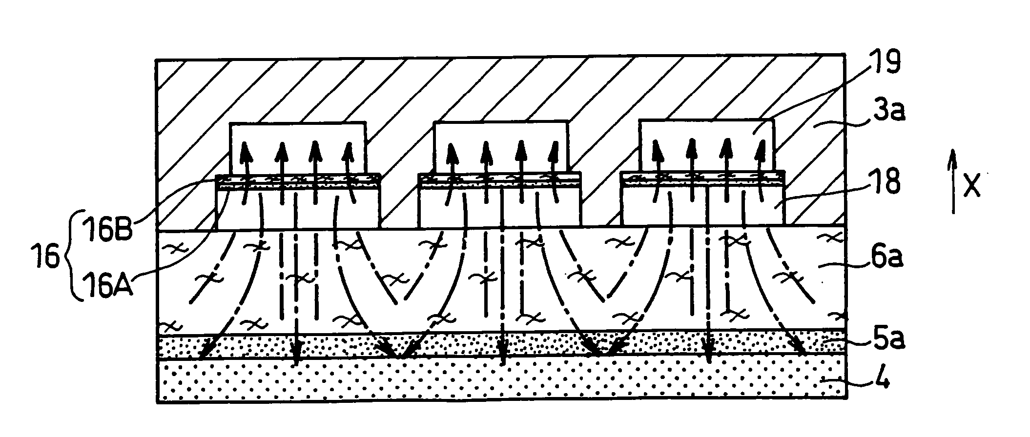
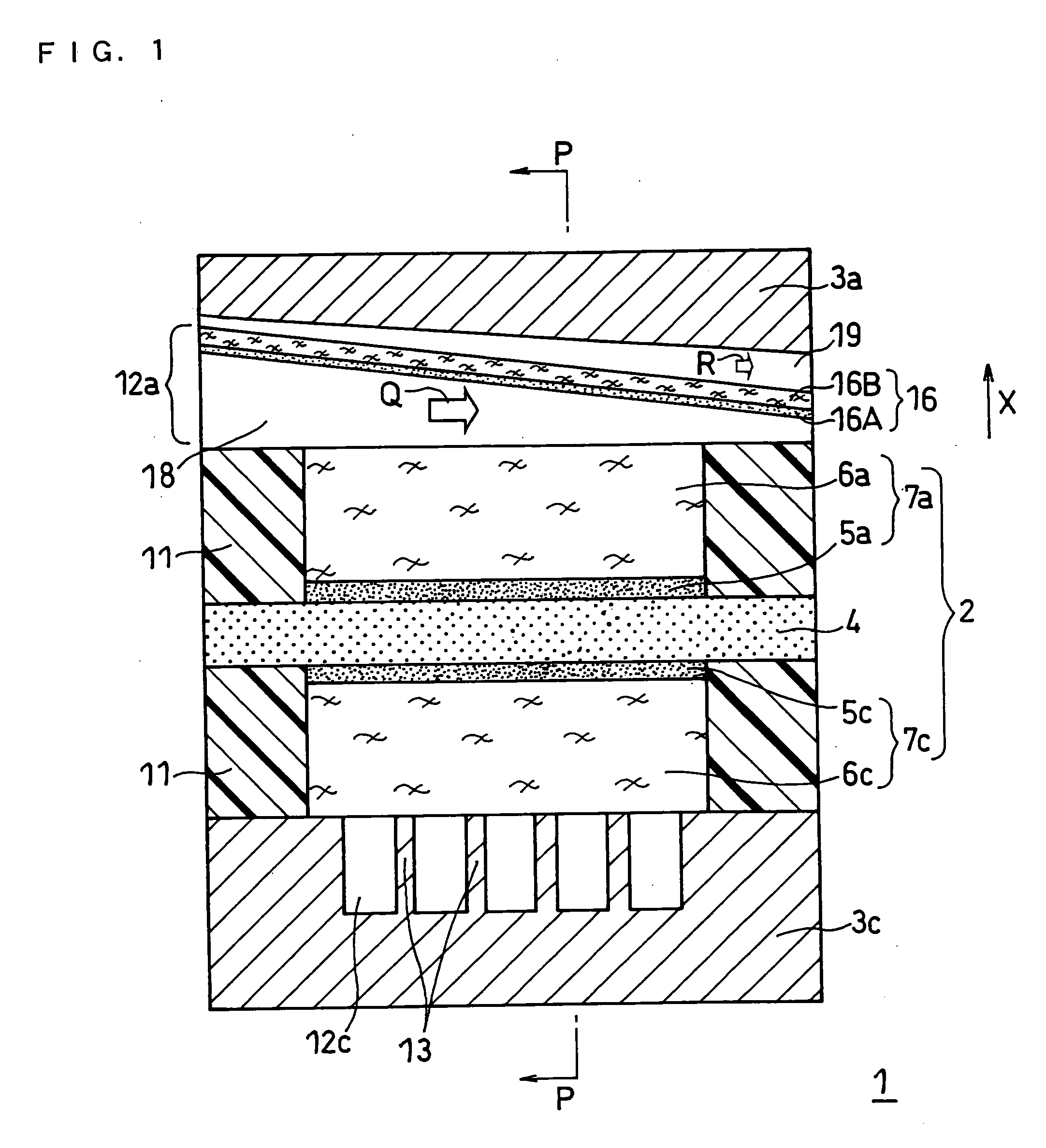
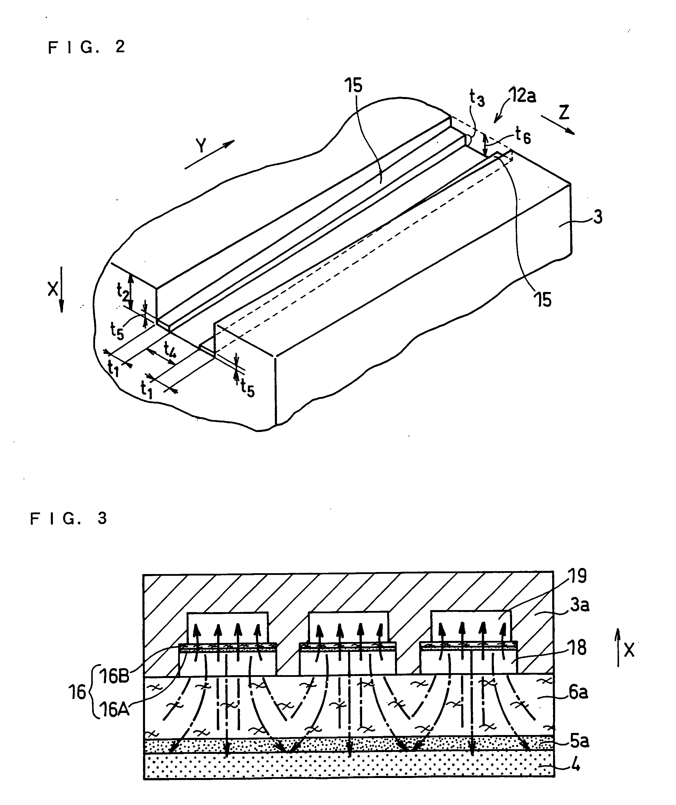
[0019] Such structure prevents carbon dioxide gas generated by electricity production to stay particularly in the anode side flow path and in the anode side diffusion layer, and especially enables to prevent a blockage of fuel supply to the anode side catalyst layer. Additionally, by dividing the anode side flow path along the direction perpendicular to the depth thereof, and by making the fuel to flow mainly in the divided portion of the flow path contacting the membrane electrode assembly, the fuel can be supplied to the anode side diffusion layer from the whole opening of the anode side flow path, and the fuel can be supplied evenly to the whole surface of the anode side catalyst layer.
[0020] Such film for the division is preferably formed of a porous body formed of at least one material selected from the group consisting of carbon, ceramic, glass, and resin, in view of further reliably minimizing deterioration of battery performance from corrosion by the fuel and from the reaction with the catalyst layer. The above film may be formed of a composite material including two or more kinds of these materials.
[0022] The porous body forming the film has micropores with gas permeability. The porous body may be a film, a sheet, or a mesh. By especially giving a water-repellency treatment to the porous body surface to form a water-repellent layer, the water-repellency ability and the liquid-repellency ability can be controlled by adjusting the thickness of and the surface form (unevenness) of the water-repellent layer. This enables the film to permeate gas while blocking a liquid fuel, and enables the control of the ratio between the speed of liquid fuel permeation and the speed of gas permeation.
[0025] Carbon dioxide generated in the anode (especially in the anode side catalyst layer) reaches the anode side flow path of the anode side separator via the anode side diffusion layer. Then, since carbon dioxide is discharged to the outside via the anode side flow path, in the anode side flow path, occupancy rate for carbon dioxide gas becomes higher at a downstream side than at an upstream side in the fuel flow direction. Therefore, in the second flow path portion in which carbon dioxide mainly flows, carbon dioxide can be discharged further smoothly when the cross sectional area substantially perpendicular to the longitudinal direction of the second flow path portion is structured to increase from an upstream side to a downstream side.
[0027] Since the amount of fuel decreases as the fuel is utilized for electricity generation, the first flow path portion in which fuel mainly flows may be structured so that the cross sectional area of the first flow path portion substantially perpendicular to the longitudinal direction thereof is decreased from an upstream side to a downstream side. Such structure enables effective space usage.
[0029] According to the present invention as described in the above, in addition to securing the fuel amount to be supplied to the anode side catalyst layer particularly, generated carbon dioxide gas can be further securely discharged, enabling to realize a direct methanol fuel cell with excellent electricity production ability.

Problems solved by technology

With mobile electronic devices such as mobile phones, personal data assistants (PDA), laptop computers, and camcorders becoming more multi-functional, power consumption and usage time for these devices increased.
However, there are some problems in practical usage of DMFC.
One of the problems is related to discharge of the reaction product, i.e., the carbon dioxide gas.
Then, the bubbles push the fuel out from the micropores of the diffusion layer, thereby causing the fuel supply for the catalyst layer to be insufficient, and a portion of unused fuel to be discharged to the outside.
As a result, the electricity production might drop greatly at a high current density side.
However, the above conventional technique is yet to be improved, in terms of providing a direct methanol fuel cell having sufficient electricity production ability without reducing fuel usage efficiency.
However, since the completely separated fuel flow path and exhaust flow path are provided at the anode side separator, when the diffusion layer is low in fuel permeability, the fuel amount to be supplied to the region in the surface of the catalyst layer facing the exhaust flow path becomes insufficient, causing a decrease in the output.

Method used


Image

  • Direct methanol fuel cell
  • Direct methanol fuel cell
  • Direct methanol fuel cell

Examples


example 2

[0095] A fuel cell was made in the same manner as Example 1 (cell 5) except that in the anode side flow path 12a of the anode side separator 3a, a starting-point height t5 of the slopes 15 was set to 0.3 mm.

example 3

[0096] A fuel cell was made in the same manner as Example 1 (cell 6) except that in the anode side flow path 12a of the anode side separator 3a, grooves with a starting-point depth (t2) of 0.6 mm, and an ending-point depth (t6) of 1 mm were formed, and a starting-point height t5 of the slopes 15 was set to 0.3 mm, and an ending-point height (t3) of the slopes was set to 0.7 mm.

example 4

[0097] A fuel cell was made in the same manner as Example 1 (cell 7) except that in the anode side flow path 12a of the anode side separator 3a, grooves with a starting-point depth (t2) of 0.6 mm, and an ending-point depth (t6) of 0.6 mm were formed, and a starting-point height t5 of the slopes 15 was set to 0.3 mm, and an ending-point height (t3) of the slopes 15 was set to 0.3 mm.


PUM


Abstract

For give a direct methanol fuel cell which secures the fuel supply to the catalyst layer, reliably discharge generated carbon dioxide gas, and has excellent electricity generation ability, at least a portion of the anode side flow path is divided by a film having water-repellency and gas permeability to a first flow path portion positioned at the membrane electrode assembly side and a second flow path portion positioned at the bottom side of the anode side flow path where a fuel mainly flows in the first flow path portion and carbon dioxide mainly flows in the second flow path portion.

Description

FIELD OF THE INVENTION [0001] The present invention relates to solid polymer electrolyte fuel cells, especially to a flow path of a separator in a direct methanol fuel cell. BACKGROUND OF THE INVENTION [0002] With mobile electronic devices such as mobile phones, personal data assistants (PDA), laptop computers, and camcorders becoming more multi-functional, power consumption and usage time for these devices increased. To provide for these increases, high energy density is strongly desired for the batteries to be mounted on these devices. Currently, lithium secondary batteries are mainly used for those devices. However, the energy density of lithium secondary batteries are predicted to reach its limit at about 600 Wh / L in around the year 2006, and for replacement, polymer electrolyte fuel cells (PEFC) are expected to be in practical use earlier. [0003] Among fuel cells, a direct methanol fuel cell (also simply referred to as DMFC hereinafter), is gaining attention and researches and ...

Claims


Application Information

Patent Timeline
IPC IPC(8): H01M8/02H01M8/10
CPCH01M8/0223H01M8/0228H01M8/0241H01M8/0258H01M8/0265H01M8/1011H01M2008/1095H01M2300/0082Y02E60/523H01M8/026Y02E60/50H01M8/02H01M8/0267H01M8/0271H01M8/241
Inventor FUKUDA, SHINSUKEUEDA, HIDEYUKI
Owner PANASONIC CORP
Learn More