System and method for improving grid efficiency utilizing statistical distribution control

a distribution control and statistical technology, applied in the field of statistical distribution control system and method for improving grid efficiency, can solve the problems of inherently inefficient, limited success of current thermal and non-thermal appliance units having energy storage systems, and difficulty in achieving high-efficiency, so as to improve the improve the effect of anticipated electric power grid conditions and reducing the demand for electric energy by end-users

Active Publication Date: 2013-05-30
GREENER ICE SPV L L C
View PDF4 Cites 45 Cited by
  • Summary
  • Abstract
  • Description
  • Claims
  • Application Information

AI Technical Summary

Benefits of technology

[0005]An embodiment of the present invention may therefore comprise: an electric controller capable of independently operating an electric appliance comprising: the controller that controls a standard operation mode and an alternate operation mode of the appliance, the controller that provides information for the timing of the standard operation mode and the alternate operation mode of the appliance by execution of operational commands for the appliance, the controller that acts in statistical coordination with additional controllers on a plurality of the appliances that collectively provide a desired load offset to improve anticipated electric power grid conditions.
[0006]An embodiment of the present invention may also comprise: an electric appliance capable of operating using standard line voltage AC electricity supplied by an electric power grid in a standard operation mode, capable of storing the AC electricity in another form of energy in a charging mode, and operating using the energy stored with the appliance in an alternate operation mode comprising: an energy storage module that converts the AC electric energy to another form of energy and stores another form of energy to create stored energy in the charging mode, the appliance that utilizes the stored energy to operate the appliance in the alternate operation mode to perform approximately the same function as the standard operation mode, thereby reducing an end-user's demand for the electric energy during the alternate operation mode; a controller that independently controls the standard operation mode, the charging mode and the alternate operation mode of the appliance, the controller that contains information for the timing of the standard operation mode, the charging mode and the alternate operation mode of the appliance by execution of operational commands for the appliance, the controller that acts in statistical coordination with additional controllers on a plurality of appliances that collectively provide a desired load offset to improve anticipated electric power grid conditions.
[0007]An embodiment of the present invention may also comprise: an electric appliance capable of operating using standard line voltage AC electricity in a standard operation mode and operating using energy stored with the appliance in an alternate operation mode comprising: a thermal energy storage module that converts electric energy to thermal energy and stores the thermal energy in a charging mode, the appliance that utilizes the stored thermal energy to change the temperature within or outside of the appliance in the alternate operation mode thereby reducing an end-user's demand for the electric energy during the alternate operation mode; a controller that independently controls operation of the thermal energy storage unit and controls the conversion of the electric energy to the thermal energy and supply of the heating or the cooling of the appliance based upon execution of operational commands, the controller that contains information for the timing of the operational commands and that acts in statistical coordination with additional controllers on a plurality of appliances that collectively provide a desired...

Problems solved by technology

Current thermal and non-thermal appliance units having energy storage systems have had limited success due to several deficiencies, including reliance on batteries which are inherently inefficient and water chillers that are practical only in large commercial ...

Method used


Image

  • System and method for improving grid efficiency utilizing statistical distribution control
  • System and method for improving grid efficiency utilizing statistical distribution control
  • System and method for improving grid efficiency utilizing statistical distribution control

Examples


Embodiment Construction

[0018]While this invention is susceptible to embodiment in many different forms, it is shown in the drawings, and will be described herein in detail, specific embodiments thereof with the understanding that the present disclosure is to be considered as an exemplification of the principles of the invention and is not to be limited to the specific embodiments described.

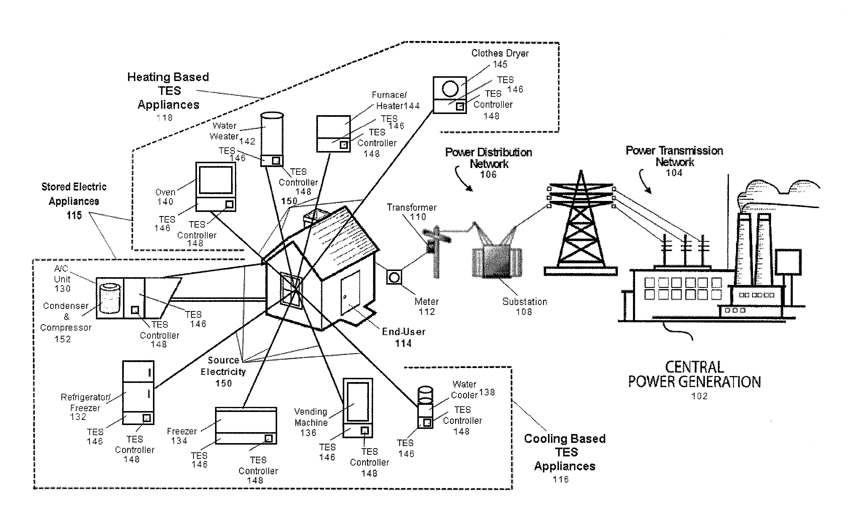
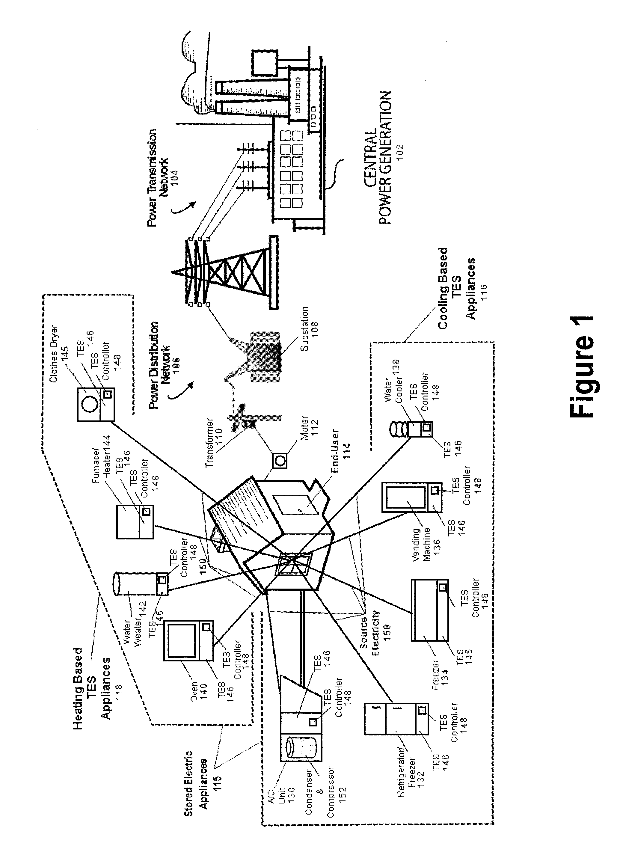
[0019]FIG. 1 illustrates an embodiment of a system for improving grid efficiency utilizing energy storage whereby a number of energy storage units located in proximity to an end-user, convert electric energy to thermal energy in one time period, store this thermal energy for an amount of time, and later supply the stored thermal energy to the end-user thereby reducing the end-user's demand for grid supplied electric energy during this second time period. This embodiment illustrates a dwelling where a plurality of stored electric appliances 115 are controlled so as to shift load away from periods of peak demand of an ele...


PUM


Abstract

Disclosed is a system and method for improving grid efficiency, reliability, security and capacity, utilizing energy storage over a plurality of on-site energy storing appliances, and also utilizing on-site demand reduction devices lacking storage, all controlled via configuration settings with a local means to act independently, yet in statistical coordination, to provide a desired effect. The appliance and controller are located on the downstream side of the end-users power meter, and facilitates the utilization of the stored energy and manages the optimal timing for producing and delivering the stored energy to the end-user. This model demonstrates a utility driven, disaggregated, distributed energy system, where the distributed energy resource is designed to behave as an offset to the predictable daily electrical demand profile.

Description

CROSS REFERENCE TO RELATED APPLICATION[0001]This application is based upon and claims the benefit of U.S. provisional application No. 61 / 490,308, entitled “System and Method for Improving Grid Efficiency Utilizing Statistical Distribution Control,” filed May 26, 2011 and the entire disclosures of which is hereby specifically incorporated by reference for all that it discloses and teaches.BACKGROUND OF THE INVENTION[0002]With the increasing stress on peak demand power consumption, Thermal Energy Storage (TES) has been utilized to shift power consumption from on-peak to off-peak times and rates. A need exists for load shifting from peak to off-peak periods to stabilize and improve electrical power grid efficiency without impacting the end-user. Current thermal and non-thermal appliance units having energy storage systems have had limited success due to several deficiencies, including reliance on batteries which are inherently inefficient and water chillers that are practical only in l...

Claims


Application Information

Patent Timeline
IPC IPC(8): H02J3/00H02J3/28
CPCH02J3/005H02J3/28H02J3/14H02J2003/003H02J2003/143G06Q50/06Y02B70/3266Y04S20/222Y04S20/242G06Q10/06Y02B70/3225H02J2310/14H02J3/003Y02B70/30
Inventor PARSONNET, BRIAN
Owner GREENER ICE SPV L L C
Why Eureka
Try Eureka