
Magnetic bead separation apparatus and method

a magnetic bead and separation apparatus technology, applied in the direction of magnetic separation, specific use bioreactor/fermenter, after-treatment of biomass, etc., to achieve the effect of rapid separation

Inactive Publication Date: 2013-05-30
BROWN UNIVERSITY
View PDF4 Cites 20 Cited by
  • Summary
  • Abstract
  • Description
  • Claims
  • Application Information

AI Technical Summary

Benefits of technology

The patent is about a method for separating samples using magnetic beads. The method involves quickly moving the beads through microfluidic channels, which helps to keep the target molecules or samples on the beads. The method also allows for the separation of large amounts of sample quickly due to the efficient use of magnetic force. The use of high viscosity fluids is recommended for this method. The speed of bead movement is important - it reduces the diffusion of material and is more efficient than other methods. The magnetic beads should move at least 0.5 mm / sec and preferably at least 0.7 mm / sec through the microchannel. Overall, this patent describes a faster and more efficient way to separate samples using magnetic beads.

Problems solved by technology

(a) It is not a standard round tube based separation technique nor does it require repeated washing / rinsing steps or excessive reagents. It does not use lateral flow.
(b) The rapid travel of magnetic beads (at least about 0.5 mm / sec and preferably at least about 0.7 mm / sec) through microchannel fluids provides limited carry-over of target or sample molecules not bound to microbeads.
(c) It does not require flow of sample solution containing target molecules. The capture / binding of spores occurs in the output reservoir, so that the method uniquely processes large amount of sample for rapid separation;

Method used


Image

  • Magnetic bead separation apparatus and method
  • Magnetic bead separation apparatus and method
  • Magnetic bead separation apparatus and method

Examples


Embodiment Construction

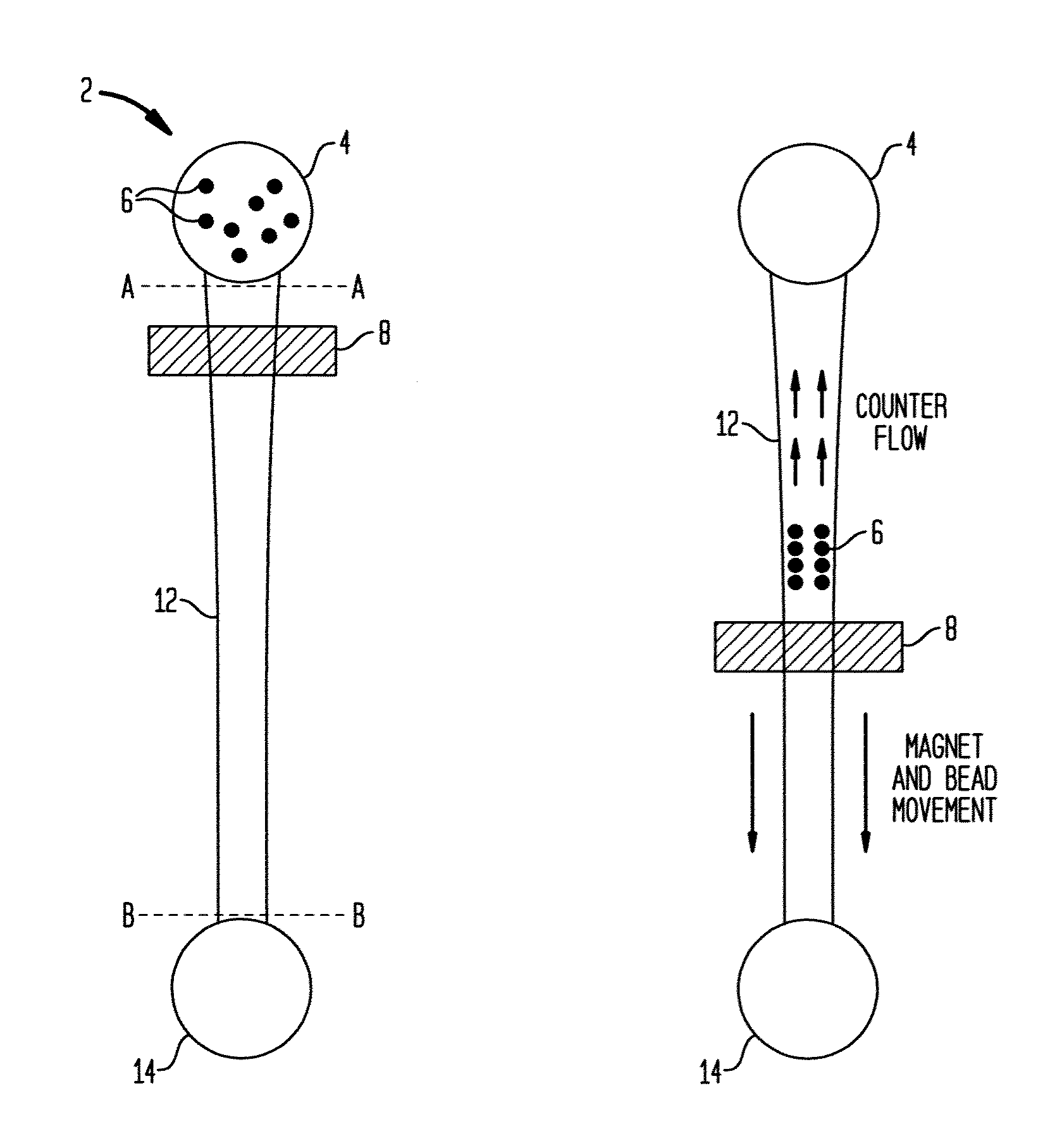
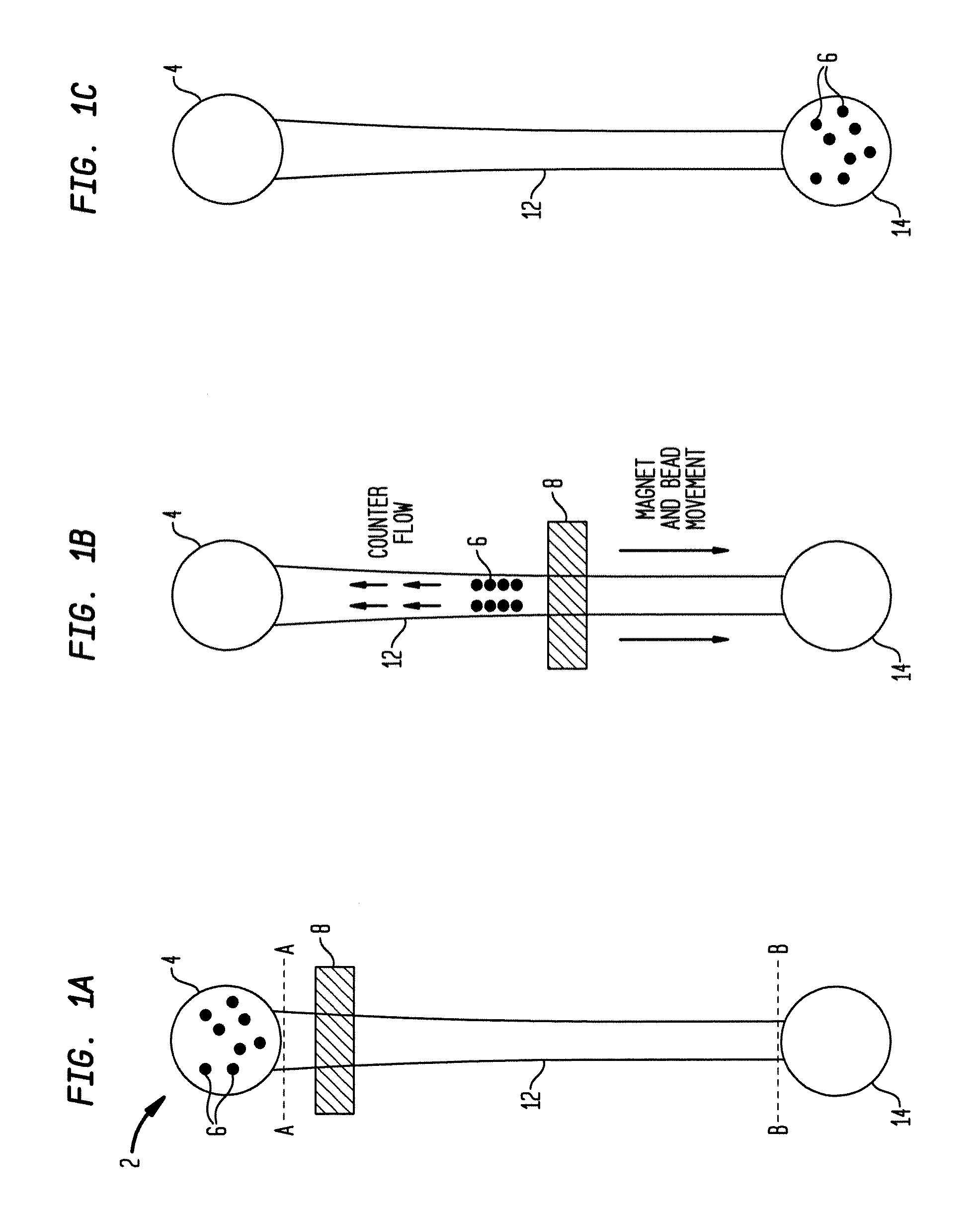
[0039]The present system provides rectangular or square microchannels of a taper design for efficient bead travel. The taper design also reduces the need for strong magnets. Further noted is the use of high viscosity liquids in channels. This avoids or reduces carryover of unwanted molecules. This is facilitated by the motive force being magnetic force or field and not (or only minimally) fluid flow. In the disclosed embodiments, individual reservoirs can be accurately temperature controlled. In one embodiment temperature control is by metal coating or film on a reactor glass cover and induction heating.

[0040]A significant aspect of this separation method is utilization of magnetic beads for bioassays, not as a static solid-support, but as a mobile platform on which multi-step microfluidic procedures are be performed. In one embodiment, magnetic beads bearing a capture antibody / nucleotide and detector antibodies / nucleotide probes are mixed in with a sample containing target molecule...


PUM

PropertyMeasurementUnit
Speedaaaaaaaaaa
Widthaaaaaaaaaa
Widthaaaaaaaaaa

Abstract

Disclosed herein is a diffusion-limiting reactor having a first element and a closure element, said reactor having at least two interconnected reservoirs said interconnection being by non-impinging microchannel, and at least one said reservoir and said microchannel being magnetic accessible. Further disclosed is a method of sample separation.

Description

CROSS-REFERENCE TO RELATED APPLICATIONS[0001]This application claims priority to copending U.S. patent application Ser. No. 13 / 660,427 filed Oct. 25, 2012 and to U.S. Patent Application Ser. No. 61 / 551,087 filed Oct. 25, 2011.SEQUENCE LISTING [0002]The instant application contains a Sequence Listing which has been submitted in ASCII format via EFS-Web and is hereby incorporated by reference in its entirety. Said ASCII copy, created on Dec. 5, 2012, is named B19729US.txt and is 2,307 bytes in size.FIELD OF THE INVENTION[0003]Disclosed herein is a diffusion-limiting reactor having a first element and a closure element, said reactor having at least two interconnected reservoirs said interconnection being by non-impinging microchannel, and at least one said reservoir and said microchannel being magnetic accessible. Further disclosed is a method of sample separation.BACKGROUND [0004]The target-probe or sample microbead diagnostic field has long sought a technology capable of the rapidly ...

Claims


Application Information

Patent Timeline
IPC IPC(8): C12Q1/68
CPCB03C1/286B03C2201/26B03C2201/18
Inventor TRIPATHI, ANUBHAVMCCALLA, STEPHANIE E.LEE, JINKEE
Owner BROWN UNIVERSITY
Learn More