Air/Fuel Ratio Controller and Control Method

a technology of air/fuel ratio controller and control method, which is applied in the direction of electrical control, process and machine control, instruments, etc., can solve the problems of loss of efficiency and failure of control, and achieve the effect of improving control quality

Active Publication Date: 2013-05-30
ALTRONIC
View PDF10 Cites 14 Cited by
  • Summary
  • Abstract
  • Description
  • Claims
  • Application Information

AI Technical Summary

Benefits of technology

[0007]According to the invention, a search for the AFR setpoint is performed in which the minimum NOx sensor output is reached. This is done with a simple but yet stable and robust control, where the system will calibrate itself. Furthermore, the invention provides robustness to ageing catalysts, in that it still finds the best operating AFR set-point. The method uses the combined properties of the combustion / catalyst / sensor in that the catalyst produces excess NH3 when the mixture is rich and the combustion produces excess NOx when the mixture is lean, whereas the sensor reacts on both species.
[0008]When a second oxygen sensor downstream of the three-way-catalyst is present, the direction of the first air / fuel ratio offset can easily determined by interpreting the oxygen sensor output as rich or lean region, whereas the air / fuel ratio offset is added in the rich direction if the output of the second oxygen sensor is interpreted as lean and vice versa.
[0009]Alternatively, the first air / fuel ratio offset is added in a predefined direction and the adding of the air / fuel ratio offset continues in the same direction if the NOx sensor output decreases or the adding of the air / fuel ratio offset continues in the opposite direction if the NOx sensor output increases. This allows a simple determination of the direction of the first air / fuel ratio offset even if no downstream oxygen sensor is available.
[0010]To ensure correct sensor readings and to improve the control quality it is advantageous that the output of the NOx sensor is allowed to stabilize for a certain time period before the next air / fuel ratio offset is added.

Problems solved by technology

An ageing catalyst may lose some efficiency which could cause the control to fail in that the predetermined window edge cannot be found at all.

Method used


Image

  • Air/Fuel Ratio Controller and Control Method
  • Air/Fuel Ratio Controller and Control Method
  • Air/Fuel Ratio Controller and Control Method

Examples


Embodiment Construction

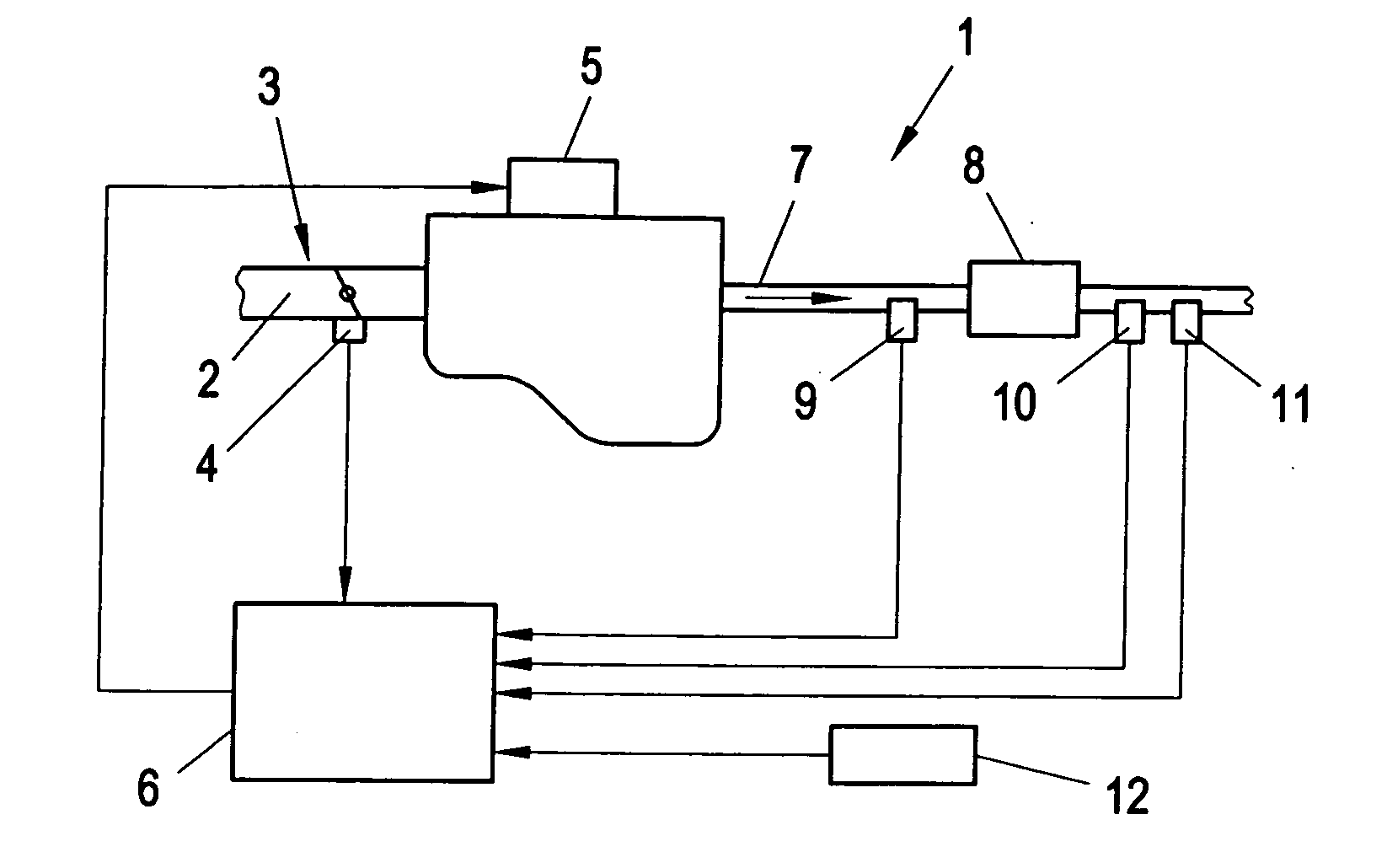
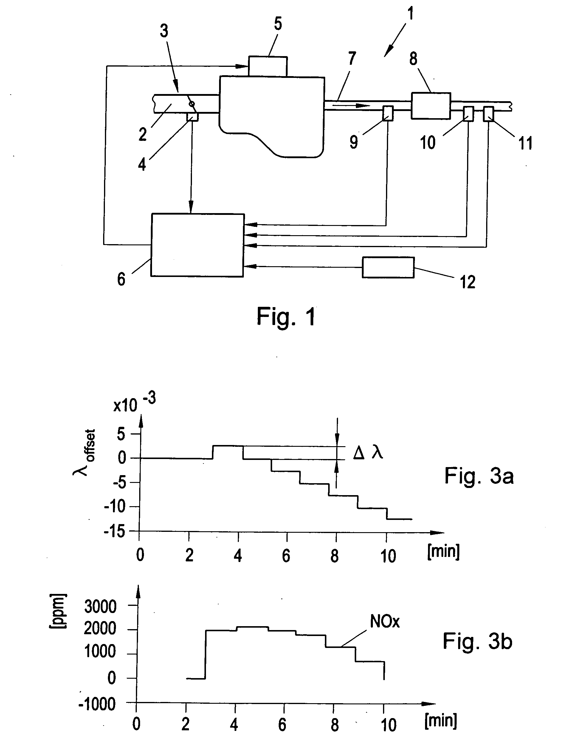
[0015]FIG. 1 shows an internal combustion engine 1 in a schematic way. As is well known, in the engine 1 a number of cylinders (not shown) are arranged in which the combustion of air / fuel mixture takes place. Air is fed to the engine 1 via an air intake line 2 in which a throttle device 3 is arranged that is controlled, e.g., by a gas pedal (not shown) or any other engine control device. The position of the throttle device may be detected by a throttle sensor 4. A fuel metering device 5 is arranged on the engine 1 which controls the amount of fuel fed to the cylinders and which is controlled by a controller 6, e.g., an ECU (engine control unit). The controller 6 calculates the optimum set-point air-fuel ratio λSP which an upstream control loop executes through operation of the fuel metering device 5 and feedback from the upstream oxygen sensor 9. The controller 6 and / or the upstream control loop that is implemented in the controller 6 may take into account the current engine 1 opera...


PUM


Abstract

An air / fuel ratio controller (6) and a method that uses an upstream control loop to maintain a given optimum air / fuel ratio (λopt), whereas the optimum air / fuel ratio (λopt) is determined in the controller (6) in an downstream control loop by adding incremental offset (Δλ) to the air / fuel ratio set-point (λSP) of an upstream control loop whilst monitoring a NOx sensor (10) output. The air / fuel ratio set-points (λSP) at two turning points (SP1, SP2) in the NOx sensor (10) output are used to calculate a new optimum air / fuel ratio set-point (λopt) as mean value of the air / fuel ratio set-points (λSP1, λSP2) at the turning points (SP1, SP2).

Description

FIELD OF THE INVENTION[0001]The present invention relates to an air / fuel ratio controller and control method for an internal combustion engine equipped with a three-way-catalyst and with an oxygen sensor upstream the three-way-catalyst and a NOx sensor downstream the three-way-catalyst.[0002]It is well known to use a three-way-catalyst (TWC) in the exhaust line of an internal combustion engine for cleaning the exhaust gas. In the TWC NOx is removed from the exhaust gas by reduction using CO, HC and H2 present in the exhaust gas, whereas CO and HC is removed by oxidation using the O2 present in the exhaust gas. A TWC works adequately only when the air / fuel ratio is kept in a rather narrow efficiency range near the stoichiometric air / fuel ratio. Therefore, an air / fuel ratio control is required in engines with a TWC.THE PRIOR ART[0003]There are many different control strategies for an air / fuel ratio control known from prior art. Also controls that use a sensor upstream of the catalyst ...

Claims


Application Information

Patent Timeline
Patent Type & Authority Applications(United States)
IPC IPC(8): F02D41/14
CPCF02D41/1461F02D41/1402F02D41/1479F02D41/1463F02D41/1441
Inventor ANDERSSON, INGEMAR
Owner ALTRONIC
Why Eureka
Try Eureka