This helps you quickly interpret patents by identifying the three key elements:
Problems solved by technology
Method used
Benefits of technology
Benefits of technology
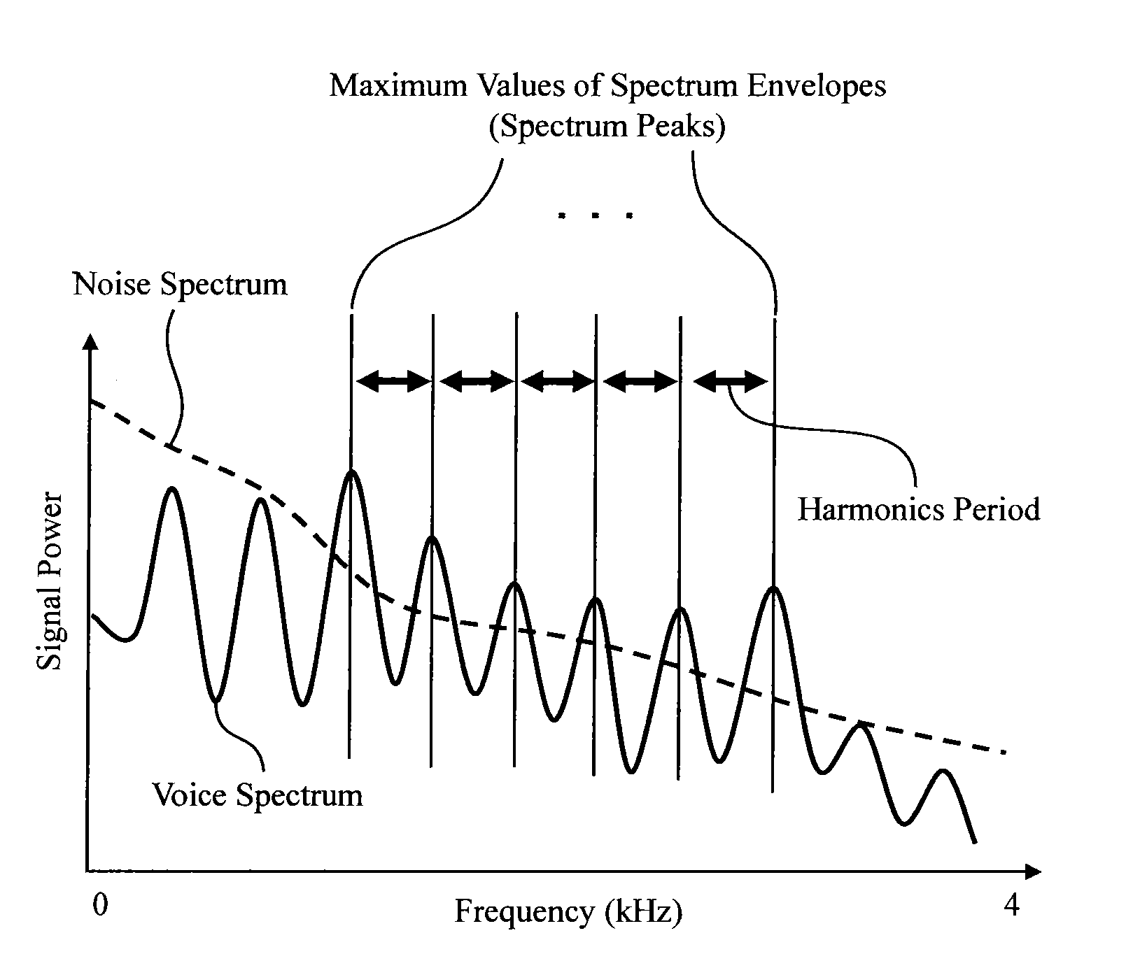
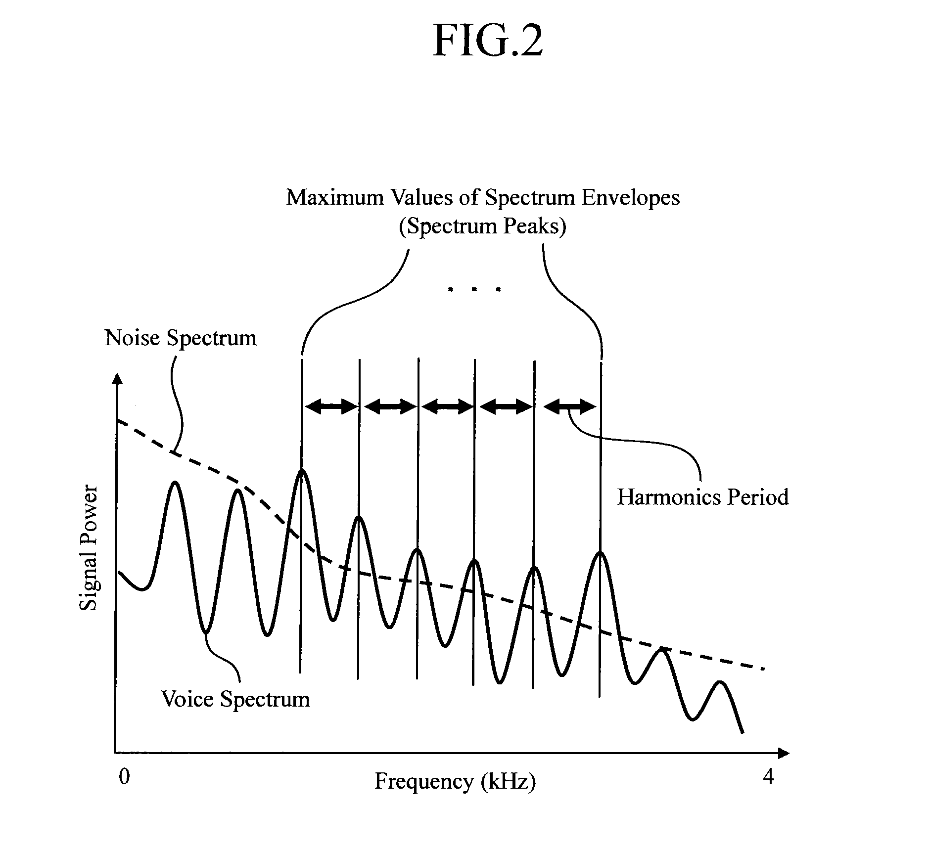
The invention provides a noise suppression device that can effectively suppress noise while maintaining the harmonic structure of voice. The device analyzes power spectra and estimates periodical information, calculates a weighting coefficient based on the periodical information and signal information, and calculates a suppression coefficient for suppressing noise based on the power spectra, the voice / noise determination unit, and the weighting coefficient. The device then identifies and suppresses the amplitudes of power spectra according to the suppression coefficient. This results in high quality noise suppression without excessive suppression of the voice.
Problems solved by technology
Therefore, when the input signal includes remaining noise, i.e., when the output signal of the noise suppression device includes the remaining noise, the low frequency region component is affected by the remaining noise.
This situation may cause a problem that the voice quality is suddenly degraded.
Further, there is a problem that a large amount of calculation and memory are required for generation of the low frequency region component, filtrationprocessing, and control of the degree of overlay of the low frequency region component.
Method used
Image
Click on the blue label to locate the original text in one second.
Reading with bidirectional positioning of images and text.
Examples
embodiment 1
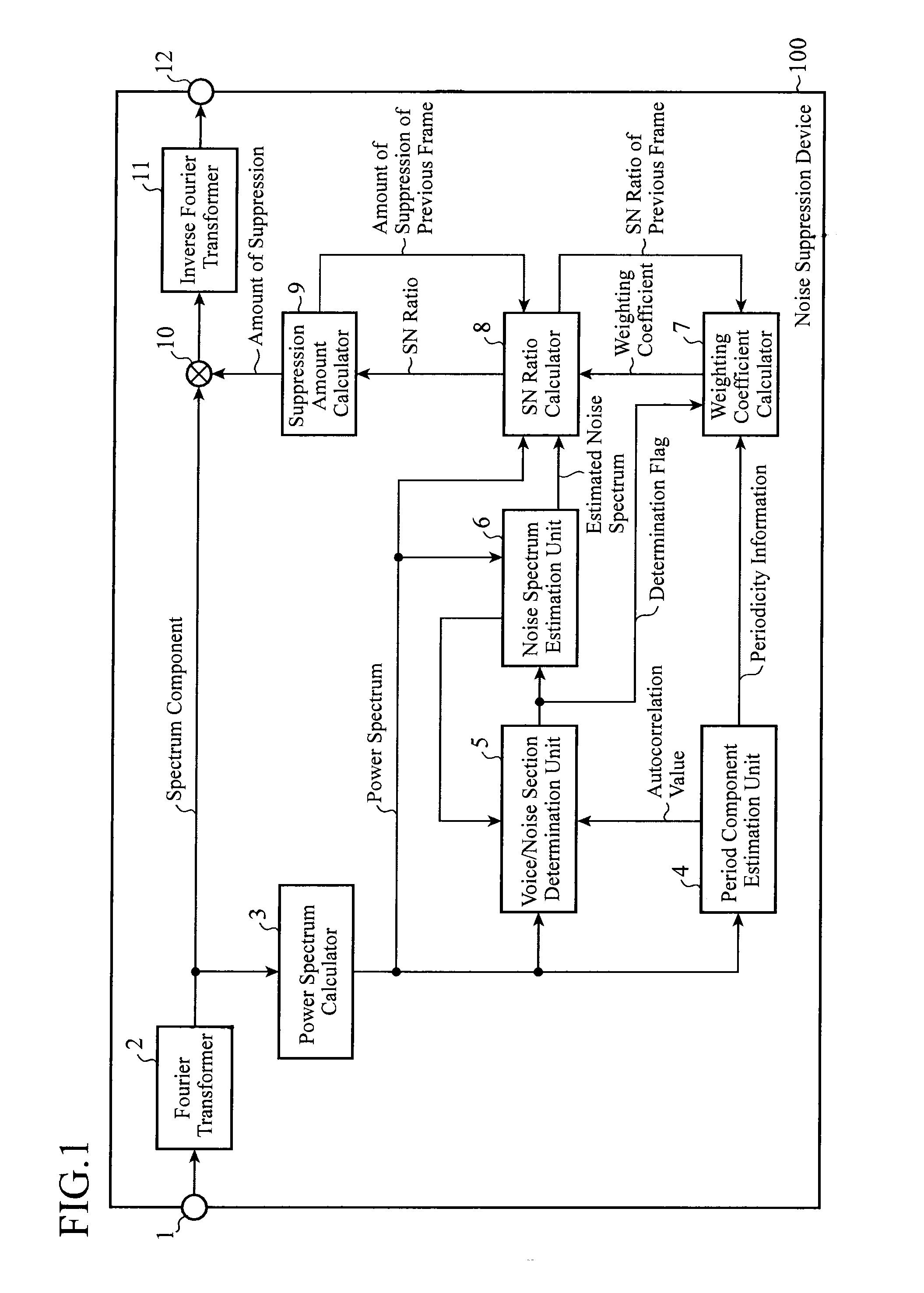
[0019]FIG. 1 is a block diagram illustrating a configuration of a noise suppression device according to Embodiment 1 of this invention.
[0020]The noise suppression device 100 includes an input terminal 1, a Fourier transformer 2, a power spectrum calculator 3, a period component estimation unit 4, a voice / noise section determination unit (voice / noise determination unit) 5, a noise spectrum estimation unit 6, a weighting coefficient calculator 7, an SN ratio calculator (suppression coefficient calculator) 8, a suppression amount calculator 9, a spectrum suppression unit 10, an inverse Fourier transformer (transformer) 11, and an output terminal 12.
[0021]Hereinafter, the principle of operation of the noise suppression device 100 will be explained with reference to FIG. 1.
[0022]Processes are preliminarily performed on voice, music, and the like retrieved through a microphone (not shown) to implement an A / D (analog / digital) conversion, a sampling at a predetermined sampling frequency (fo...
embodiment 2
[0061]In Embodiment 1 explained above, the value of weighting is kept in constant along a frequency direction as shown in the formula (9). Embodiment 2 presents a configuration for making the value of weighting different in a frequency direction.
[0062]For example, as a general feature of voice, the harmonic structure in the low frequency region is clear. Therefore, the weighting may be increased in the low frequency region, whereas the weighting can be decreased as the frequency increases. Constituent elements of the noise suppression device according to Embodiment 2 are the same as those of Embodiment 1, and explanation thereabout is omitted.
[0063]As described above, Embodiment 2 is configured such that different weighting is applied for each frequency in estimation of the SN ratio. Therefore, suitable weighting can be achieved for each frequency of voice, and still higher quality noise suppression can be achieved.
embodiment 3
[0064]Embodiment 1 explained above shows a configuration in which the value of weighting is a predetermined constant as shown in the formula (9). Embodiment 3 presents a configuration in which multiple weighting constants are switched in accordance with an index of voice probability as to an input signal, or are controlled through a predetermined function.
[0065]The index of voice probability as to the input signal, that is, a control factor of mode of the input signal, may be configured such that, when the maximum value of the autocorrelation coefficient is high in the formula (4), that is, when the period structure of the input signal is clear (i.e. it is highly possible that the input signal is voice), the weighting may be increased, whereas the weighting may be decreased when the period structure of the possibility is low. Alternatively, the autocorrelation function and the voice / noise section determination flag may be used together. Constituent elements of the noise suppression ...
PUM
Abstract
A noise suppression device includes: a power spectrum calculator converting an input signal of time domain into power spectra of frequency domain; a voice / noise determination unit determining whether the power spectra indicate voice or noise; a noise spectrumestimation unit estimating noise spectra of the power spectra; a period component estimation unit analyzing a harmonic structure constituting the power spectra and estimating periodical information about the power spectra; a weighting coefficient calculator calculating a weighting coefficient for weighting the power spectra; a suppression coefficient calculator calculating a suppression coefficient for suppressing noise included in the power spectra; a spectrum suppression unit suppressing amplitude of the power spectra in accordance with the suppression coefficient; and an inverse Fourier transformer converting the power spectra output by the spectrum suppression unit into a signal of time domain to generate a noise-suppressed signal.
Application Information
Patent Timeline
Application Date:The date an application was filed.
Publication Date:The date a patent or application was officially published.
First Publication Date:The earliest publication date of a patent with the same application number.
Issue Date:Publication date of the patent grant document.
PCT Entry Date:The Entry date of PCT National Phase.
Estimated Expiry Date:The statutory expiry date of a patent right according to the Patent Law, and it is the longest term of protection that the patent right can achieve without the termination of the patent right due to other reasons(Term extension factor has been taken into account ).
Invalid Date:Actual expiry date is based on effective date or publication date of legal transaction data of invalid patent.

