Load distribution system

a load distribution and storage system technology, applied in the field of storage systems, can solve the problems of ineffective addressing of workload balancing among storage systems, ineffective approach to adding flash memory, and difficulty in determining which storage system should receive the added resource, so as to minimize non-user capacity, and improve the utilization efficiency of high-performance resources

Inactive Publication Date: 2013-05-30
HITACHI LTD
View PDF19 Cites 30 Cited by
  • Summary
  • Abstract
  • Description
  • Claims
  • Application Information

AI Technical Summary

Benefits of technology

[0003]Exemplary embodiments of the invention provide load distribution among storage systems using solid state memory (e.g., flash memory) as expanded cache area. In a system, some appliances have solid state memory second cache feature in the pool. These appliances may be referred to FM (Flash Memory) appliances and they are shared in usage by a plurality of DKCs (Disk Controllers). During normal workload, each DKC processes all I / O inside itself. In case of high workload (e.g., the amount of first DRAM cache dirty data in DKCs become too much) in a DKC, the DKC distributes the load to the appliance. After the high workload quiets down or subsides toward the normal workload, that DKC will stop distributing the load to the appliance. By sharing the FM appliance among a plurality of storage systems, (i) utilization efficiency of high-performance resources is improved (storage systems' timings of high-workload are different); (ii) high-performance resources' capacity utilization efficiency is improved (it is possible to minimize non-user capacity such as RAID parity data or spare disks); and (iii) it becomes easier to design to improve performance (user will just add appliance in the pool).

Problems solved by technology

Workload balancing among storage systems is not effective in addressing the issue of sudden or periodical short term spike in workload.
For a storage system, this approach of adding flash memory is not efficient because the flash memory is not shared among the plurality of storage systems.
Furthermore, it is difficult to determine which storage system should receive the added resource (i.e., flash memory as a second cache) and how much resource to add.
This approach of adding flash memory to the appliance allows shared use of the added flash memory in the storage caching appliance among storage systems but the range is limited by the scale of the appliance.
Moreover, the approach is not efficient in the case of low or normal workload (normal state).

Method used


Image

  • Load distribution system
  • Load distribution system
  • Load distribution system

Examples


first embodiment

I. First Embodiment

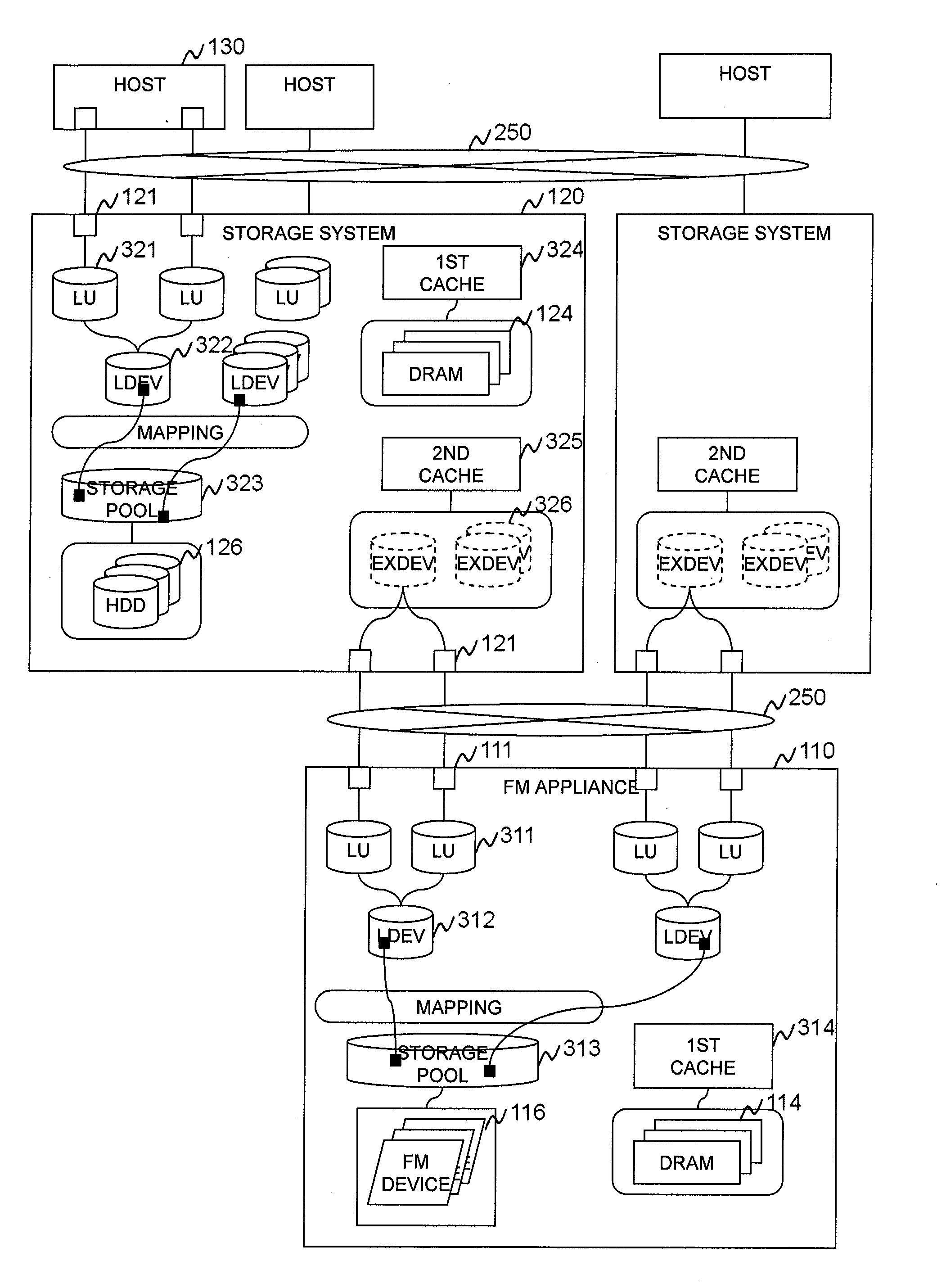
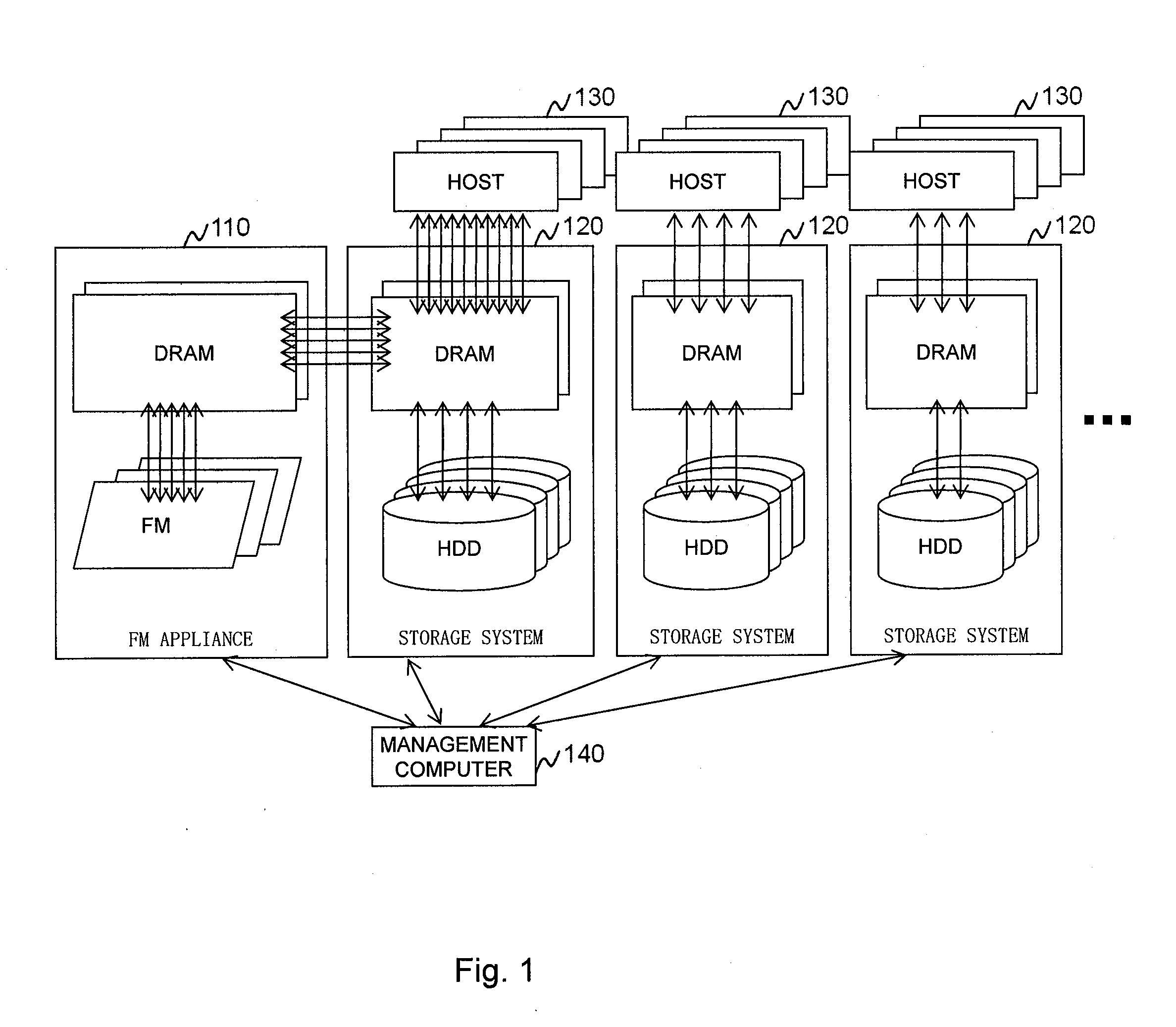
[0092]FIG. 1 illustrates an example of a hardware configuration of an information system in which the method and apparatus of the invention may be applied. The information system includes a plurality of storage systems 120 and a FM appliance 110 that has high performance media devices such as flash memory (FM) devices. The appliance 110 is shared in usage by the storage systems 120. A management computer 140 collects and stores the workload information from each storage system 120 and the FM appliance 110. During normal (lower) workload, each storage system 120 processes I / O from hosts 130 inside itself. In case of high workload in a storage system 120 (amount / ratio of DRAM cache dirty data in storage system 120 becomes too much), that storage system 120 distributes the load to the appliance 110. After the high workload quiets down or subsides, the storage system 120 will stop distributing the load to the appliance 110.

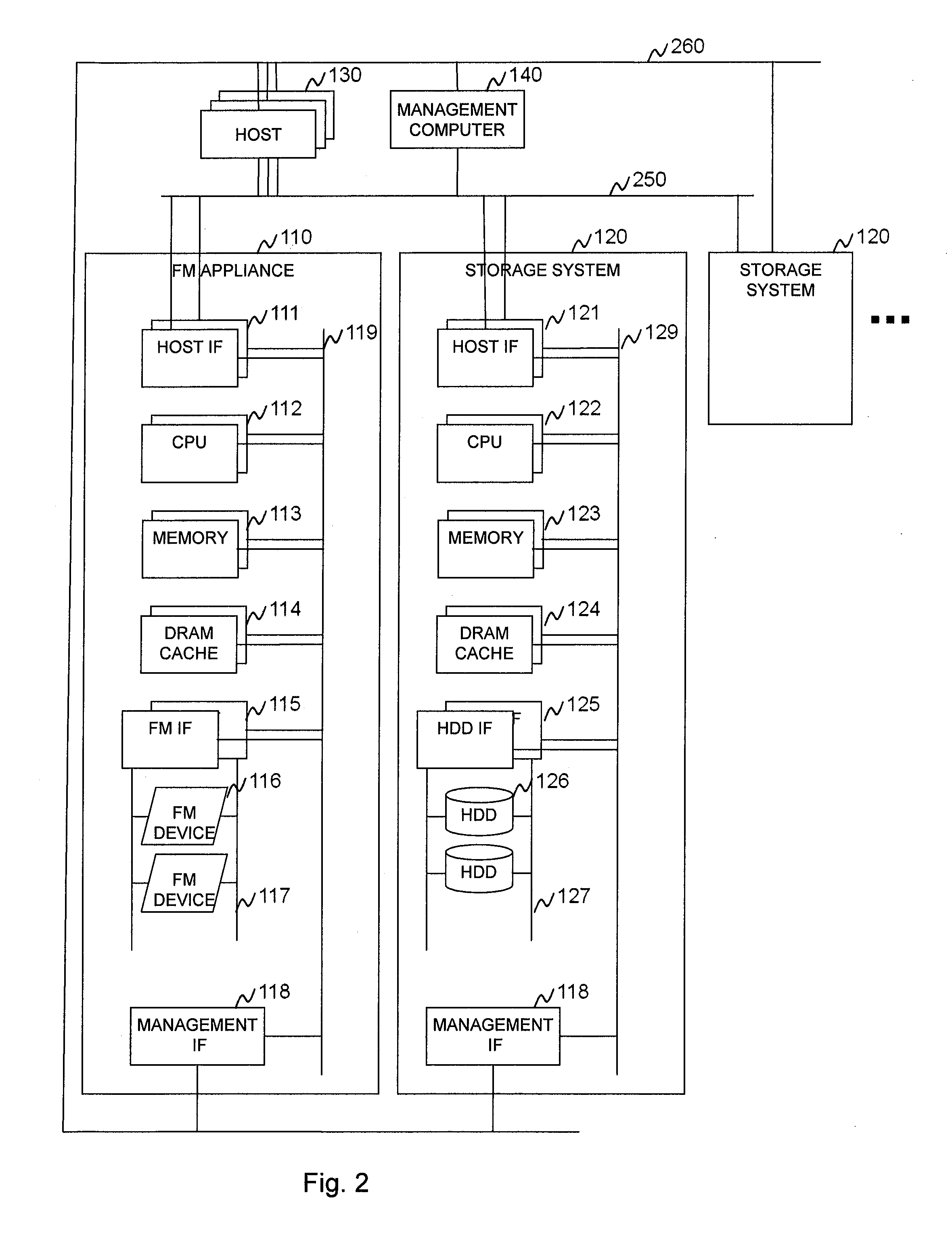
[0093]FIG. 2 illustrates further details of t...

second embodiment

II. Second Embodiment

[0119]In the second embodiment, the storage system doubles as FM appliance. The storage system can have FM devices inside itself and uses them as permanent areas and / or second cache areas. In case of high workload, the storage system distributes other storage systems that have enough clean first cache area and second cache free area.

[0120]FIG. 14 illustrates an example of a hardware configuration of an information system according to the second embodiment.

[0121]FIG. 15 illustrates further details of the physical system configuration of the information system of FIG. 14 according to the second embodiment. The storage system can have FM devices inside itself and use them as permanent areas and / or second cache areas.

[0122]FIG. 21 illustrates an example of a logical configuration of the invention according to the second embodiment. Only the differences from the first embodiment of FIG. 3 are described here. The storage systems may have and use internal FM devices as...

third embodiment

III. Third Embodiment

[0128]In the third embodiment, external appliance is used as expanded first cache area.

[0129]FIG. 16 illustrates an example of a hardware configuration of an information system according to the third embodiment. In case of high workload, the storage system uses the FM appliance as expanded first cache area. The storage system directly forwards received write data to the FM appliance (internal first cache-throw).

[0130]FIG. 26 illustrates an example of a logical configuration of the invention according to the third embodiment. One difference from the first embodiment of FIG. 3 is that the first cache of the storage system in FIG. 26 consists of internal DRAM and external devices. External first cache technology written in this embodiment may also apply to the first embodiment (external device as 2nd cache) and the second embodiment (using internal FM device as permanent and second cache, storage systems use other storage systems' resources with respect to each oth...


PUM


Abstract

Exemplary embodiments of the invention provide load distribution among storage systems using solid state memory (e.g., flash memory) as expanded cache area. In accordance with an aspect of the invention, a system comprises a first storage system and a second storage system. The first storage system changes a mode of operation from a first mode to a second mode based on load of process in the first storage system. The load of process in the first storage system in the first mode is executed by the first storage system. The load of process in the first storage system in the second mode is executed by the first storage system and the second storage system.

Description

BACKGROUND OF THE INVENTION[0001]The present invention relates generally to storage systems and, more particularly, to load distribution among storage systems using high performance media (e.g., flash memory).[0002]In conventional technology, each storage system is designed according to its peak workload. Recently, virtualization technology such as resource pool is used to accommodate the growth of customers' requirements in usage efficiency and cost reduction. There is a trend for more efficient usage of high performance media such as flash memories. Workload balancing in a storage system for long term trend is one virtualization feature. An example involves automated page-based tiering among media (e.g., flash memory, SAS, SATA). At the same time, it is desirable to accommodate short term change (spike) in workload and improve utilization among the plurality of storage systems. Workload balancing among storage systems is not effective in addressing the issue of sudden or periodica...

Claims


Application Information

Patent Timeline
Patent Type & Authority Applications(United States)
IPC IPC(8): G06F12/08G06F12/00
CPCG06F12/0866G06F2212/214G06F2212/262G06F2212/261G06F2212/222
Inventor KAWAMURA, SHUNJI
Owner HITACHI LTD
Why Eureka
Try Eureka