
LNG Boiloff Gas Recondensation Configurations And Methods

a liquid natural gas and recondensation configuration technology, applied in the direction of liquefaction, container discharge methods, lighting and heating apparatus, etc., can solve the problems of significant challenges in storage and transfer of lng, significant increase in bog production upon lng, and generally relatively low rate of bog production, etc., to achieve large surge volume, power saving, and small capacity

Active Publication Date: 2013-06-06
FLUOR TECH CORP
View PDF7 Cites 37 Cited by
  • Summary
  • Abstract
  • Description
  • Claims
  • Application Information

AI Technical Summary

Benefits of technology

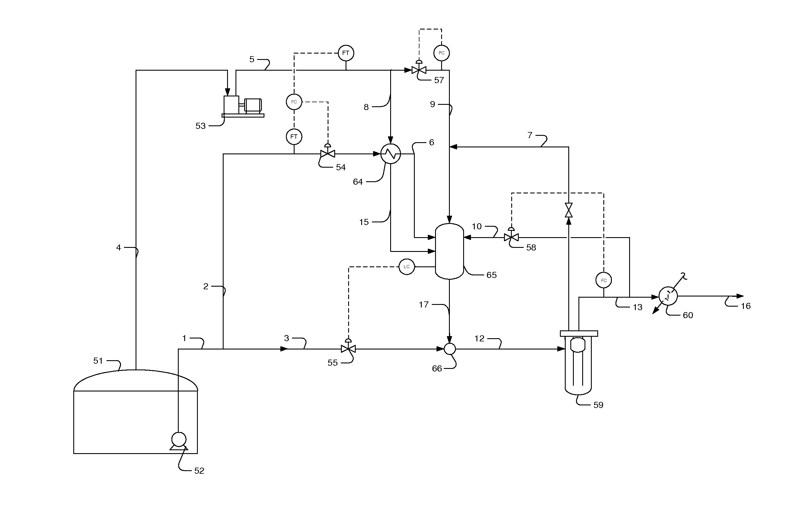
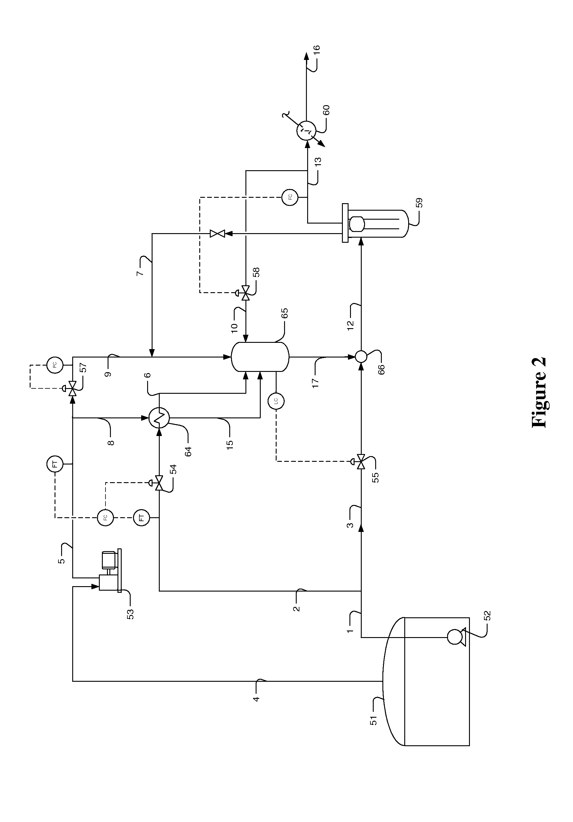
The invention relates to the use of a portion of a liquefied natural gas (LNG) sendout to condense the boil-off gas (BOG) produced in a storage tank. The combined stream of BOG and LNG sendout is then subcooled and recombined with the rest of the LNG sendout using a high pressure pump. This allows for the immediate mixing of the streams, avoiding the need for large surge volumes. The use of the portion of the LNG sendout also decouples the operation of the BOG condensing and subcooling system from the rate of the remaining LNG sendout, reducing the need for a large recondenser or a mixing vessel. This eliminates power savings and more efficient operation.

Problems solved by technology

The storage and transfer of LNG poses significant challenges, particularly with respect to LNG vapor in the form of boiloff gas (BOG).
While LNG is stored in a tank, the rate of BOG production is generally relatively low.
However, the rate of BOG production is significantly increased upon LNG transfer into the tank, mostly due to heat from the sendout pumps and thermal losses in transfer.
If the surge volume is inadequate, vapor may be introduced into the high pressure pump, which may cause cavitation in the pump, leading to component damage, decreased efficiency, and an ultimately shortened pump life.
The variable production of BOG in the tank means variability in the amount of LNG sendout required in the recondenser operation and difficulty in optimizing the system for safe operation of the high pressure pump.
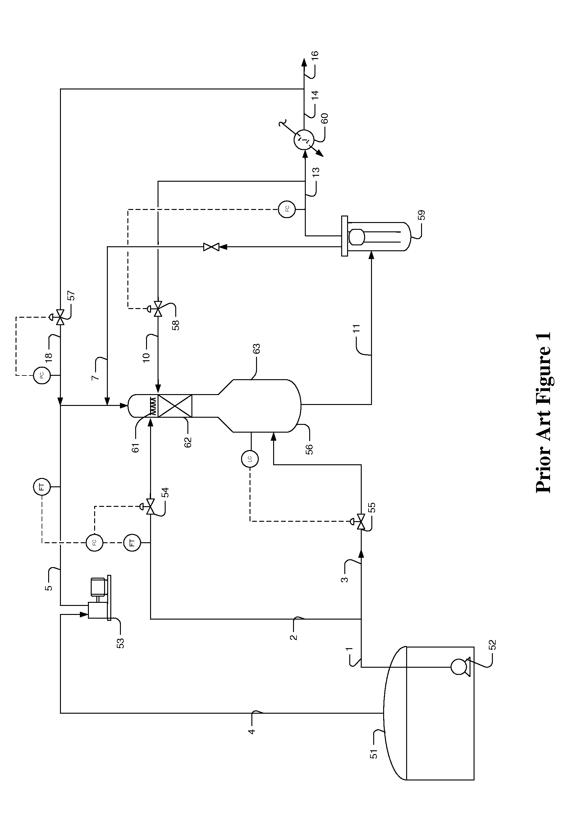
While such recondenser may allow for at least some reduction in equipment size, the volume of held up liquid in the bottom section is still considerable.
These systems described above fall short of a comprehensive and effective solution to all of the problems associated with BOG during LNG storage and transfer, especially as it relates to combination of the BOG condensate with the LNG sendout, and accommodation of large volume changes in the BOG.

Method used


Image

  • LNG Boiloff Gas Recondensation Configurations And Methods
  • LNG Boiloff Gas Recondensation Configurations And Methods
  • LNG Boiloff Gas Recondensation Configurations And Methods

Examples


Embodiment Construction

[0029]The inventor has now discovered that recondensation systems for boiloff gas (BOG) in liquid natural gas (LNG) storage tanks may be improved where processing the BOG is decoupled from the flow rate of sendout LNG from the tank by combining subcooled BOG condensate with the sendout LNG. Most preferably, the BOG is condensed and subcooled using refrigeration content of a portion of the sendout LNG, while the balance of the sendout LNG is sent to a high pressure pump. After the BOG is condensed and subcooled, the subcooled BOG / LNG stream is then combined with the balance of the sendout LNG to provide a combined subcooled sendout stream that is then fed to the high pressure pump. Decoupling of the condensing and subcooling system from the LNG sendout rate advantageously allows reduction, or even elimination, of the need for large volumes of subcooled liquid in the recondensation system to ensure the safety of the high pressure pump. The high pressure pump is fed, at a minimum, from...


PUM


Abstract

Systems and methods for optimizing the recondensation of boiloff gas in liquid natural gas storage tanks are presented. In especially preferred aspects of the inventive subject matter, BOG from a storage tank is condensed using refrigeration content of a portion of LNG sendout in a direct or indirect manner, and the BOG condensate and LNG sendout portion are combined to form a subcooled stream that is then combined with the balance of the LNG sendout, to be fed to a high pressure pump. Contemplated recondensation operations advantageously occur without using otherwise needed large volume recondensers. Moreover, the condensing and subcooling operations are decoupled from the LNG sendout rate.

Description

[0001]This application claims the benefit of priority to U.S. Provisional Application Nos. 61 / 566,155, filed on Dec. 2, 2011; 61 / 568,970, filed on Dec. 9, 2011; and 61 / 605,976, filed on Mar. 2, 2012, all of which are incorporated by reference herein.FIELD OF THE INVENTION[0002]The field of the invention is liquid natural gas (LNG) vapor handling, and especially as it relates to vapor recondensation during LNG storage, ship unloading, and transfer operations.BACKGROUND[0003]The storage and transfer of LNG poses significant challenges, particularly with respect to LNG vapor in the form of boiloff gas (BOG). While LNG is stored in a tank, the rate of BOG production is generally relatively low. However, the rate of BOG production is significantly increased upon LNG transfer into the tank, mostly due to heat from the sendout pumps and thermal losses in transfer. The variation in the amount of BOG in the tanks must be taken into account in the recondensation processes that recapture the B...

Claims


Application Information

Patent Timeline
Patent Type & Authority Applications(United States)
IPC IPC(8): F25J1/00
CPCF25J1/0025F17C2270/0136F17C2201/0104F17C2201/032F17C2201/052F17C2205/0326F17C2221/033F17C2223/0161F17C2223/033F17C2223/043F17C2223/047F17C2227/0135F17C2227/0178F17C2227/0393F17C2250/0626F17C2250/0636F17C2260/035F17C2265/022F17C2265/034F17C2265/035F17C2265/037F17C9/04F17C9/02
Inventor MAK, JOHN
Owner FLUOR TECH CORP
Learn More