Two-phase fuel injection valve for diesel engine and gas engine including nozzle having pumping function

a fuel injection valve and two-phase technology, which is applied in the direction of fuel injecting pumps, liquid fuel feeders, machines/engines, etc., can solve the problems of reducing the durability of the nozzle portion in the opening and closing needle, the inability to actively cope with pressure above the opening pressure, and the inability to achieve man-b&w approach, etc., to achieve significant industrial application, reduce harmful gas, and improve fuel efficiency

Active Publication Date: 2013-06-06
HYUNDAI HEAVY IND CO LTD
View PDF29 Cites 8 Cited by
  • Summary
  • Abstract
  • Description
  • Claims
  • Application Information

AI Technical Summary

Benefits of technology

[0017]As described above, the present invention has advantages in that a fuel injection apparatus used in an engine which uses dual fuel does not require two separate pumps and one pumping structure is operated within a valve so as to move two needles in the one pumping structure, thereby enabling pumping at high pressure and enabling pumping dual fuel at high pressure for injection.
[0018]Also, the present invention has a significant industrial applicability since the present invention has advantages in that two kinds of subsequent fuel are injected, without mixing, to an inside of a combustion chamber to be combusted such that a combustion pattern using two kinds of fuel, i.e., marine diesel oil (MDO) +heavy fuel oil (HFO) and MDO +gas fuel is achieved, thereby reducing harmful gas (smoke, Nox) within the combustion chamber and improving fuel efficiency.

Problems solved by technology

Also, even after the fuel injection is finished, a space (SAC volume) between the closed needle valve and the nozzle hole is large such that residue fuel remaining in this space flows into the cylinder, thereby causing the problem as described above.
Also, in the MAN-B&W approach, a needle valve in a slide type is adopted to reduce the SAC volume; however, the MAN-B&W approach has limitation in that pressure above the opening pressure cannot be actively coped with.
Also, in a case of the medium sized engine, the above described MAN-M&W approach and the Wartsila-Sulzer approach are complemented by creating an injection hole to be located near a combustion chamber to a maximum extent in order to reduce the SAC volume, which causes a problem in that durability of a nozzle portion in opening and closing the needle is degraded.
Namely, the above described approaches have disadvantageous in that, as shown in FIG. 8, in order to open at a predetermined pressure, spring pressure is increased and fuel pressure is manipulated to increase to adjust the opening pressure in a device other than the fuel valve (i.e., pressure is not increased by the fuel valve itself but increased by using an additional pump located in front of an entrance of the fuel valve), and only one kind of fuel is used.
Also, a fuel injection valve in a dual fuel type as dual fuel injection apparatuses 1, 2 shown in a lower portion of FIG. 8, two cylinders are operated such that two governors and two linkages are required, and two high pressure pumps are required in order to form high pressure of primary fuel and secondary fuel, and a separate line for cooling needs to be formed within an injector, thereby causing a complex structure.

Method used


Image

  • Two-phase fuel injection valve for diesel engine and gas engine including nozzle having pumping function
  • Two-phase fuel injection valve for diesel engine and gas engine including nozzle having pumping function
  • Two-phase fuel injection valve for diesel engine and gas engine including nozzle having pumping function

Examples


Embodiment Construction

[0051]Hereinafter, exemplary embodiments of the present invention will be described herein below with reference to the accompanying drawings. Further, in the following description of the present invention, a detailed description of associated known functions or elements will be omitted when it may make the subject matter of the present invention rather unclear.

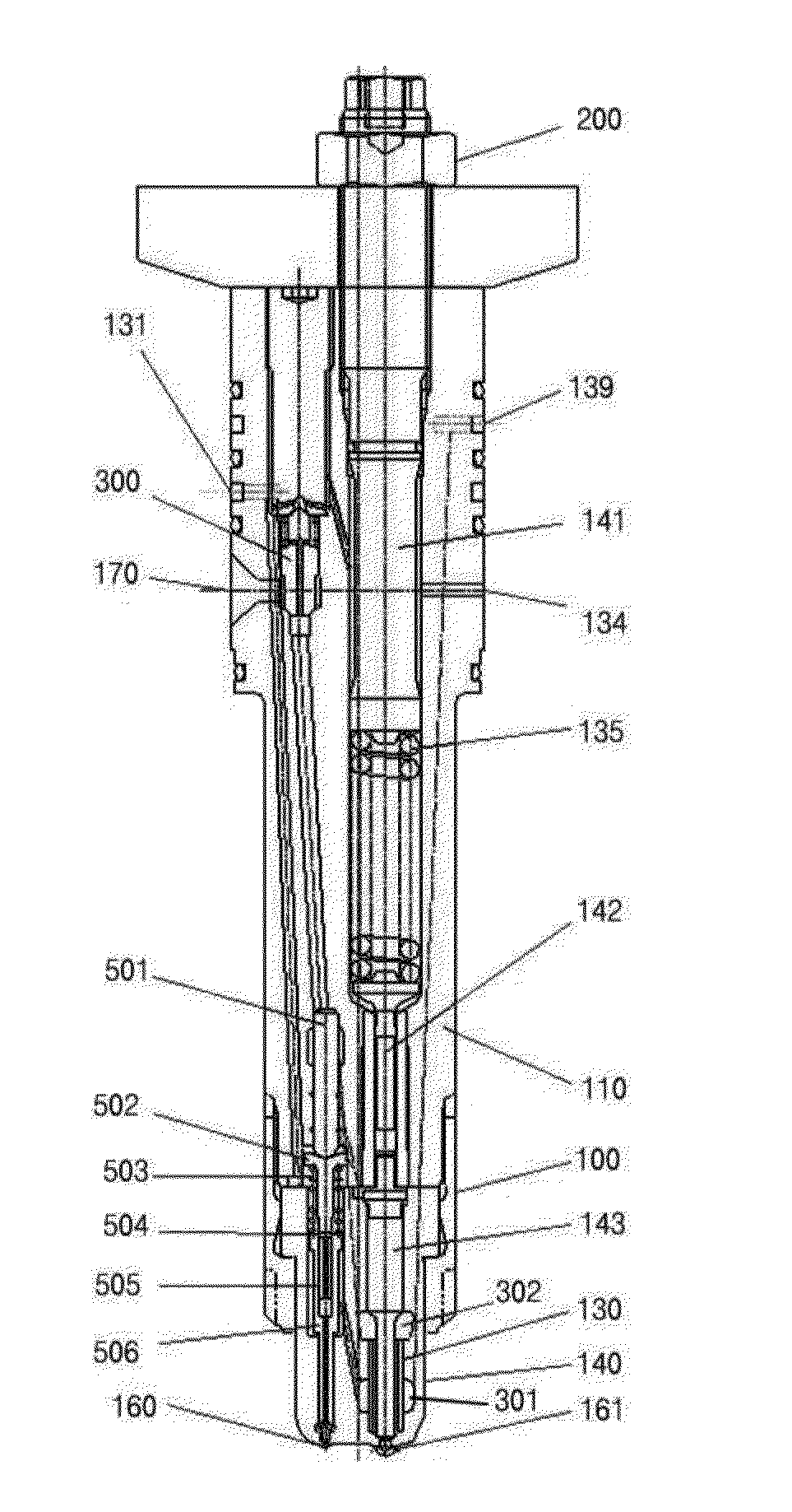
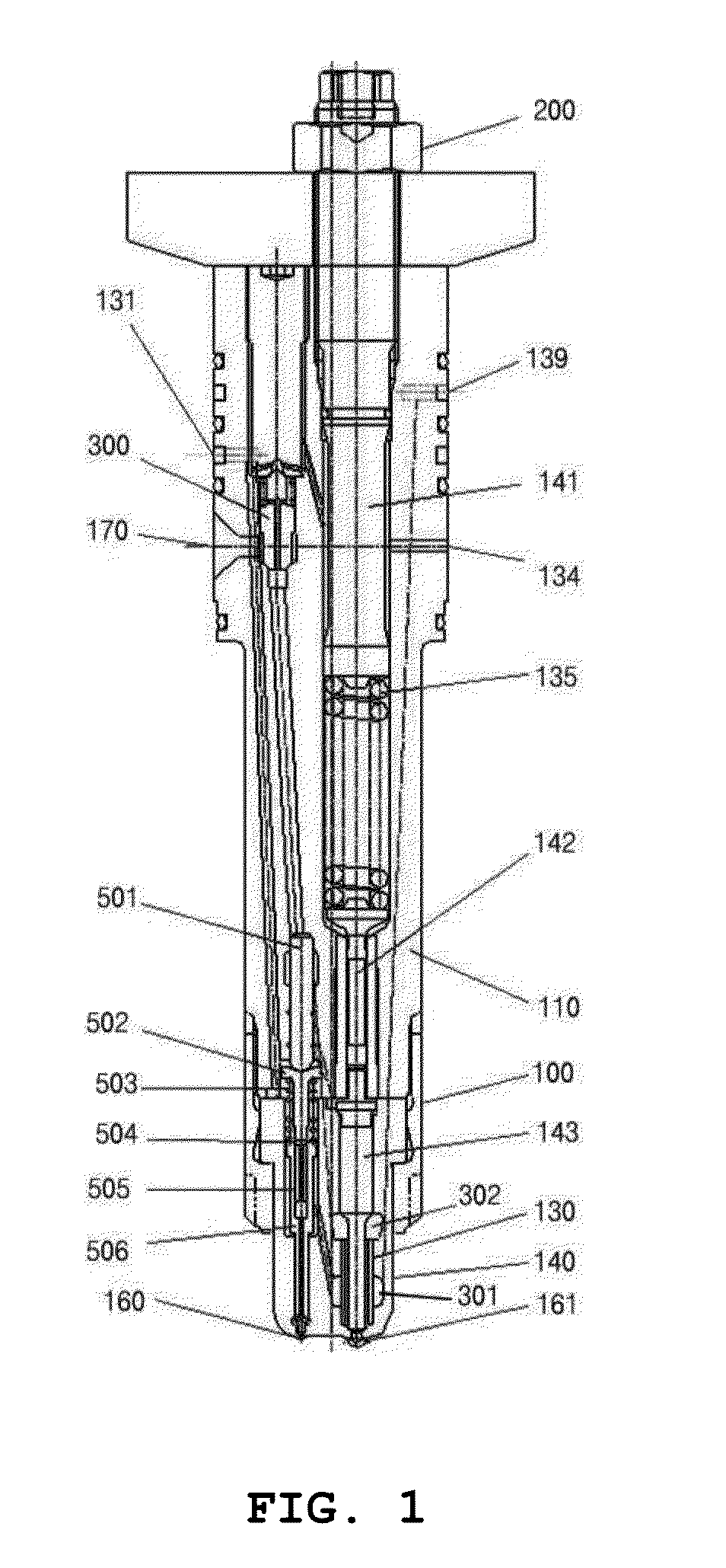
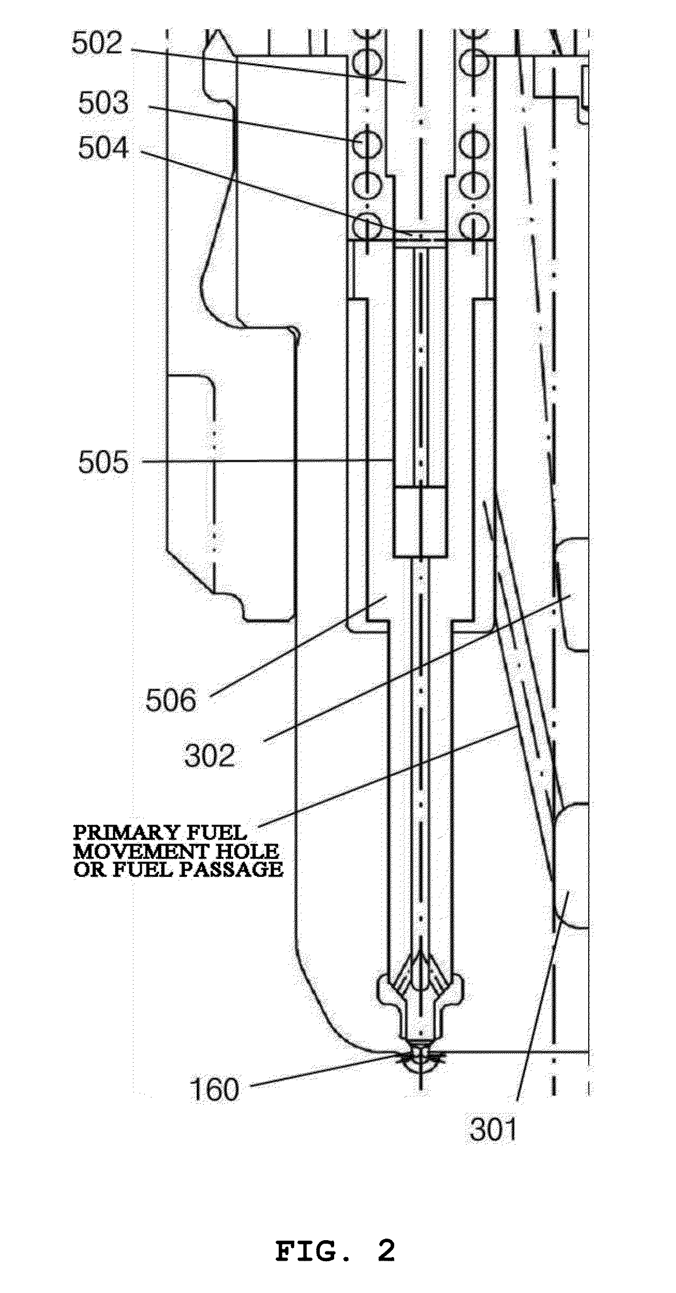
[0052]FIG. 1 is an example cross sectional view illustrating an exemplary embodiment of the present invention and FIG. 2 is an enlarged view of a portion of FIG. 1. As illustrated, the configuration of the present invention relates to a fuel injection valve capable of injecting fuel of the same system or dual fuel and is applied to an engine using the dual fuel by injecting two kinds of fuel from one valve and two pipes within a fuel injection valve which injects fuel to a cylinder according to pressure of fuel discharged from a fuel pump or a gas pipe and tension of a spring in an engine for a large vessel, a medium sized eng...


PUM


Abstract

The present invention relates to a dual fuel injection valve having a pumping nozzle for a diesel engine and a gas engine, and an objective of the present invention is to provide a fuel injection valve in which, by using two kinds of fuel entering into a fuel valve, a warming up and injection of pilot fuel may be performed in an initial injection and injection of main fuel may be performed subsequently such that subsequent dual fuel is used for combustion, thereby increasing fuel injection performance.
In a fuel injection valve for a diesel engine or a gas engine for injecting fuel to a cylinder, provided is a dual fuel injection valve having a pumping nozzle for the diesel engine and the gas engine including: the dual fuel injection valve including a fuel valve block (110) in which a fuel passage to which first and secondary fuel is introduced through a high pressure pipe is formed inside thereof, the first and secondary fuel being the same fuel system or different fuel systems; a cylinder/needle valve (506) which moves upward by a pressure difference of the secondary fuel introduced through the fuel passage formed in the fuel valve block (110) to inject the primary fuel to a pilot nozzle hole; and a main needle valve (143) which, after injecting the primary fuel by pressing the cylinder/needle valve (506), moves upward by the pressure difference of the secondary fuel introduced through a connected fuel passage to inject the primary fuel to a main nozzle hole (161).

Description

TECHNICAL FIELD[0001]The present invention relates to a dual fuel injection valve having a pumping nozzle for a diesel engine and a gas engine and, more particularly, to a hybrid fuel injection valve which enables primary injection of primary fuel by using an internal pumping structure instead of using an external pressure pump and uses pressure used for primary fuel injection as pump pressure for secondary fuel injection.BACKGROUND ART[0002]Generally, a conventional diesel engine has one needle valve and one spring, wherein the needle valve is opened when fuel of higher pressure than opening pressure is introduced and is closed when the fuel of lower pressure than the opening pressure is introduced. In this manner, when fuel of high pressure formed in a fuel pump enters to a fuel valve, if the pressure of the fuel in the fuel valve is higher than the opening pressure, the spring lifts the needle valve against a force pressing against the needle valve through pressure of fuel oil, s...

Claims


Application Information

Patent Timeline
Patent Type & Authority Applications(United States)
IPC IPC(8): F02M59/00
CPCF02D19/081F02M43/04F02M45/086F02M61/10F02M2200/44F02M59/00F02D19/061F02D19/0642F02D19/0689F02D19/0694Y02T10/36Y02T10/30
Inventor PARK, DEUK-JINKIM, EUNG-SUNGKIM, JU-TAEHEO, KWANG-CHEOLKIM, JONG-SUKHA, EUN
Owner HYUNDAI HEAVY IND CO LTD
Why Eureka
Try Eureka