Heat Exchanger for Vehicle

a technology for heat exchangers and vehicles, applied in the direction of lighting and heating apparatus, process and machine control, instruments, etc., can solve the problems of complex layout, increased composition of constituent elements and assembling processes, and inability to control the heat exchange efficiency according to the flow amount of operating fluid, etc., to improve the temperature responsiveness of deformable parts

Active Publication Date: 2013-06-06
HYUNDAI MOTOR CO LTD
View PDF25 Cites 23 Cited by
  • Summary
  • Abstract
  • Description
  • Claims
  • Application Information

AI Technical Summary

Benefits of technology

[0012]Various aspects of the present invention provide for a heat exchanger for a vehicle having further advantages of improving fuel economy and heating performance by controlling temperatures of operating fluids according to condition of the vehicle, and of reducing assembling processes by simplifying a structure of the heat exchanger.
[0030]The heat exchanger may further include a sealing for preventing the operating fluid from leaking from the connecting pipe, and the sealing may be mounted between the mounting portion and the inserting portion.
[0032]The end cap may be provided with a penetration hole for coping with a pressure changing according to flowing amount of the operating fluid flowing in through the inflow port and flowing the operating fluid in the deformable member so as to improve temperature responsiveness of the deformable member.

Problems solved by technology

Therefore, constituent elements and assembling processes increase and layout is complicated.
If additional bifurcation circuits and valves are not used, heat exchanging efficiency cannot be controlled according to flow amount of the operating fluid.
Therefore, the temperature of the operating fluid cannot be controlled efficiently.

Method used


Image

  • Heat Exchanger for Vehicle
  • Heat Exchanger for Vehicle
  • Heat Exchanger for Vehicle

Examples


Embodiment Construction

[0050]Reference will now be made in detail to various embodiments of the present invention(s), examples of which are illustrated in the accompanying drawings and described below. While the invention(s) will be described in conjunction with exemplary embodiments, it will be understood that present description is not intended to limit the invention(s) to those exemplary embodiments. On the contrary, the invention(s) is / are intended to cover not only the exemplary embodiments, but also various alternatives, modifications, equivalents and other embodiments, which may be included within the spirit and scope of the invention as defined by the appended claims.

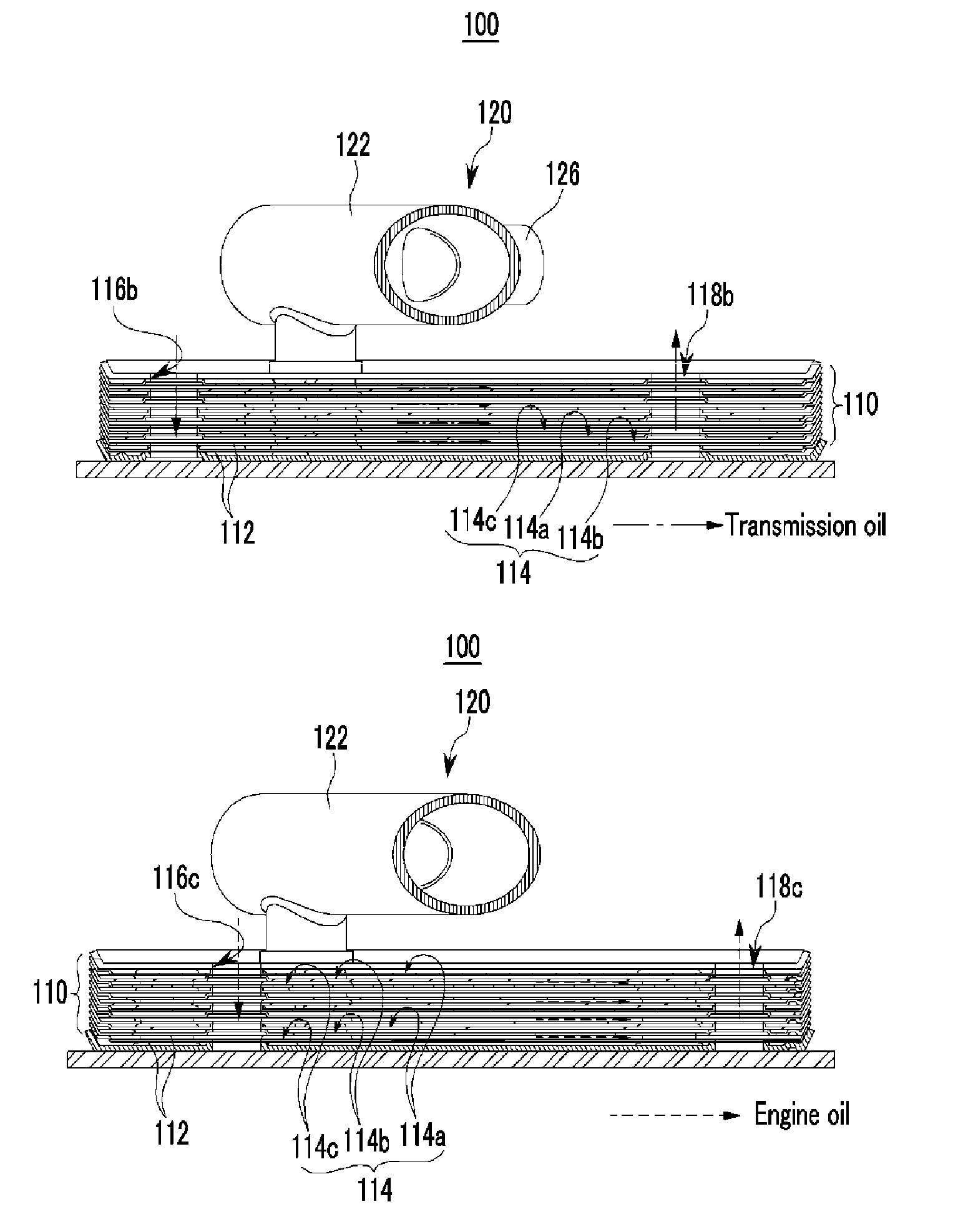
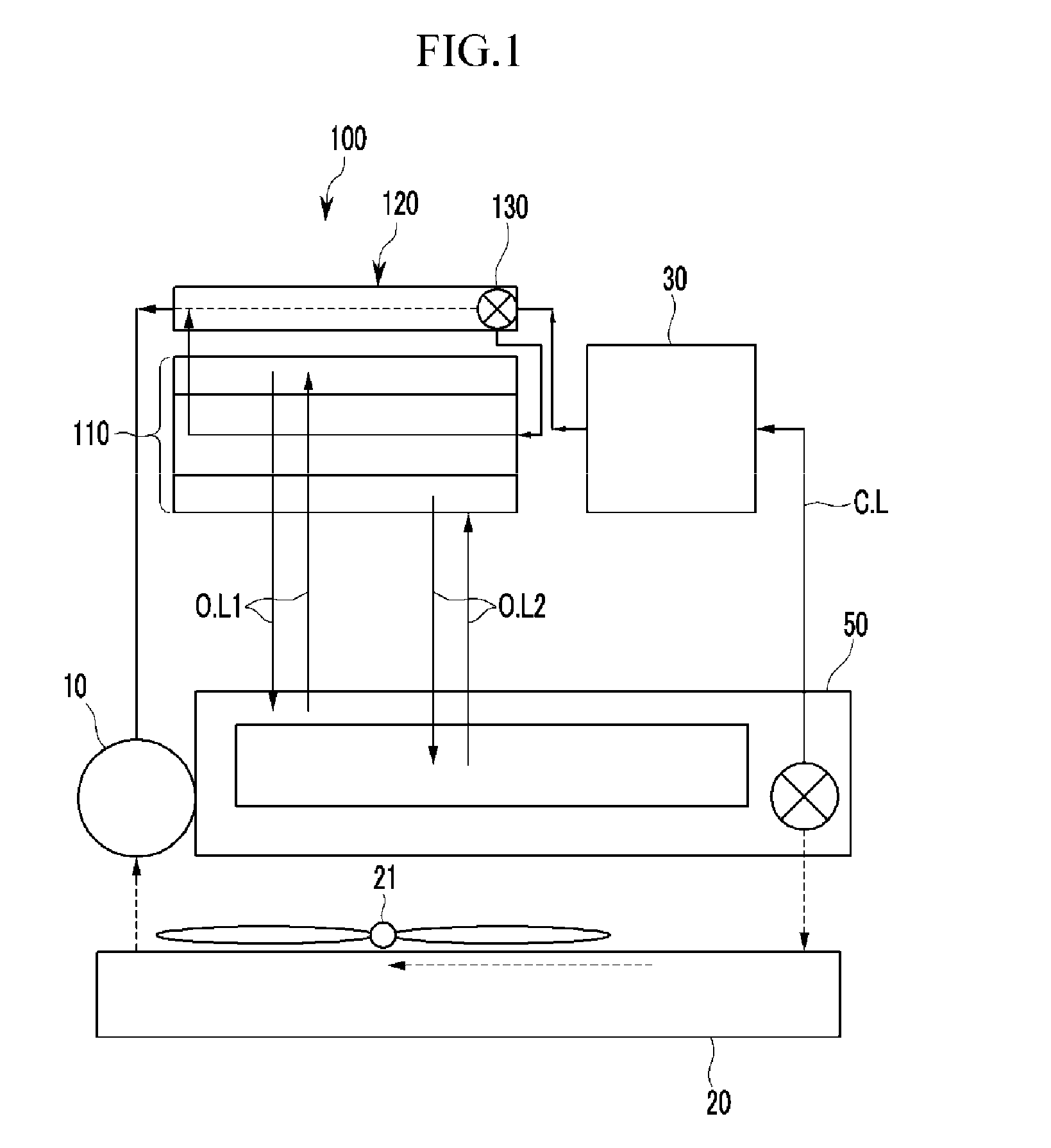
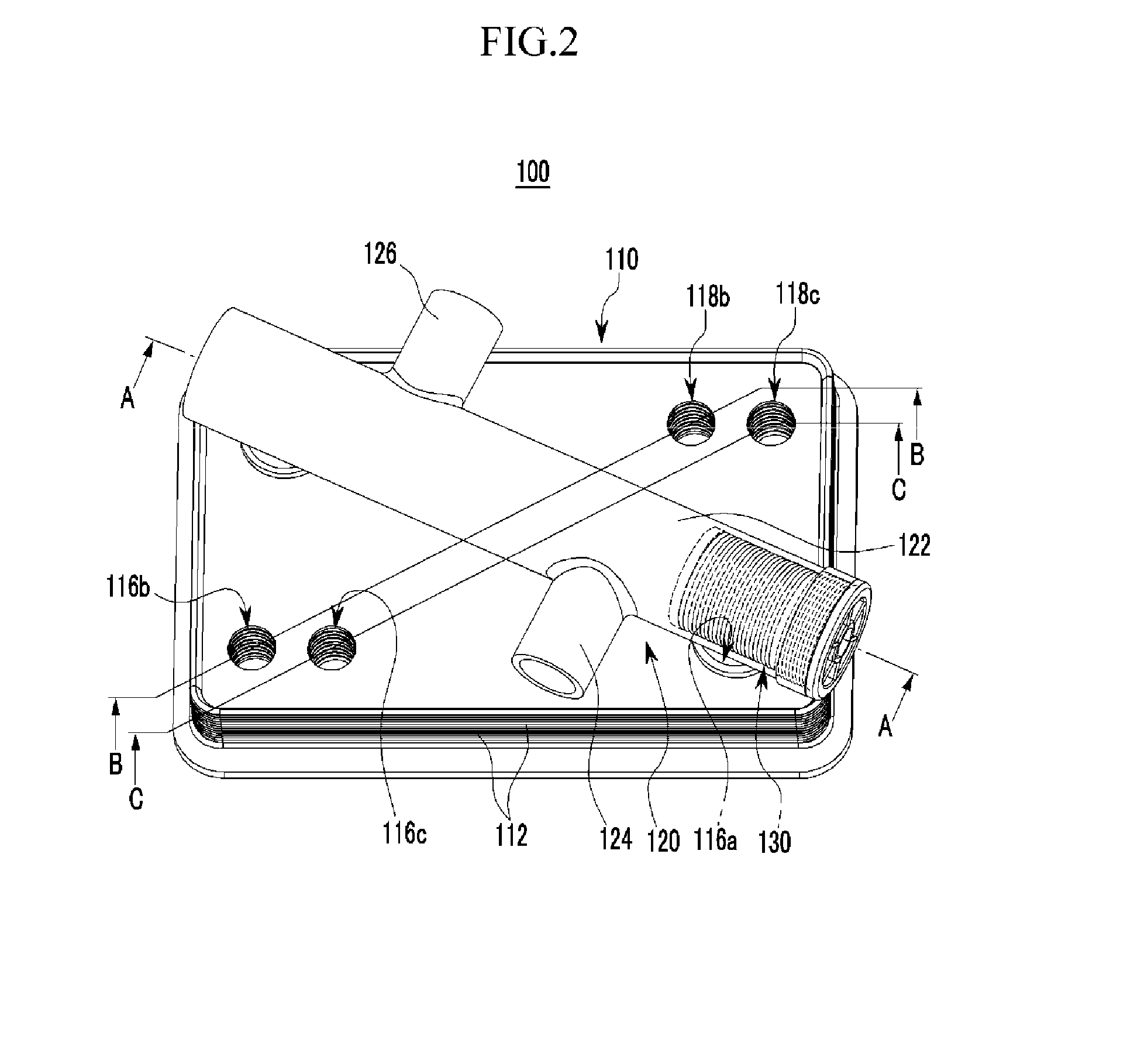
[0051]FIG. 1 is a schematic diagram of a cooling system of an automatic transmission to which a heat exchanger for a vehicle according to various embodiments of the present invention is applied; FIG. 2 is a perspective view of a heat exchanger for a vehicle according to various embodiments of the present invention; FIG. 3 is a cross-s...


PUM


Abstract

A heat exchanger may include a heat radiating portion provided with first, second, and third connecting lines formed in a predetermined sequence by stacking a plurality of plates, and receiving first, second, and third operating fluids respectively into the first, second, and third connecting lines, the first, second, and third operating fluids exchanging heat with each other while passing through the first, second, and third connecting lines and the first, second, and not being mixed with each other while being circulated, and a bifurcating portion connecting an inflow hole for flowing one operating fluid of the first, second, and third operating fluids with an exhaust hole for exhausting the one operating fluid, adapted for the one operating fluid to bypass the heat radiating portion according to a temperature of the one operating fluid, and mounted at an exterior of the heat radiating portion.

Description

CROSS-REFERENCE TO RELATED APPLICATION[0001]The present application claims priority of Korean Patent Application Number 10-2011-0129814 filed Dec. 6, 2011, the entire contents of which application is incorporated herein for all purposes by this reference.BACKGROUND OF INVENTION[0002]1. Field of Invention[0003]The present invention relates to a heat exchanger for a vehicle. More particularly, the present invention relates to a heat exchanger for a vehicle which can control temperatures of operating fluids which flows in the heat exchanger.[0004]2. Description of Related Art[0005]Generally, a heat exchanger transfers heat from high-temperature fluid to low-temperature fluid through a heat transfer surface, and is used in a heater, a cooler, an evaporator, and a condenser.[0006]Such a heat exchanger reuses heat energy or controls a temperature of an operating fluid flowing therein for demanded performance. The heat exchanger is applied to an air conditioning system or a transmission oi...

Claims


Application Information

Patent Timeline
Patent Type & Authority Applications(United States)
IPC IPC(8): G05D23/02F28F3/08
CPCF28F27/02F28D9/005F16K31/002F01M5/002F28D2021/0089F01P2060/04F01P2060/045F28D9/0093B60H1/00B60H1/02F28D1/02F28D9/00F28F3/02F28F3/08F28F27/00
Inventor KIM, JAE YEON
Owner HYUNDAI MOTOR CO LTD
Why Eureka
Try Eureka