

Electrolyser module
- Summary
- Abstract
- Description
- Claims
- Application Information
AI Technical Summary
Benefits of technology
Problems solved by technology
Method used
Image

Examples
example 1
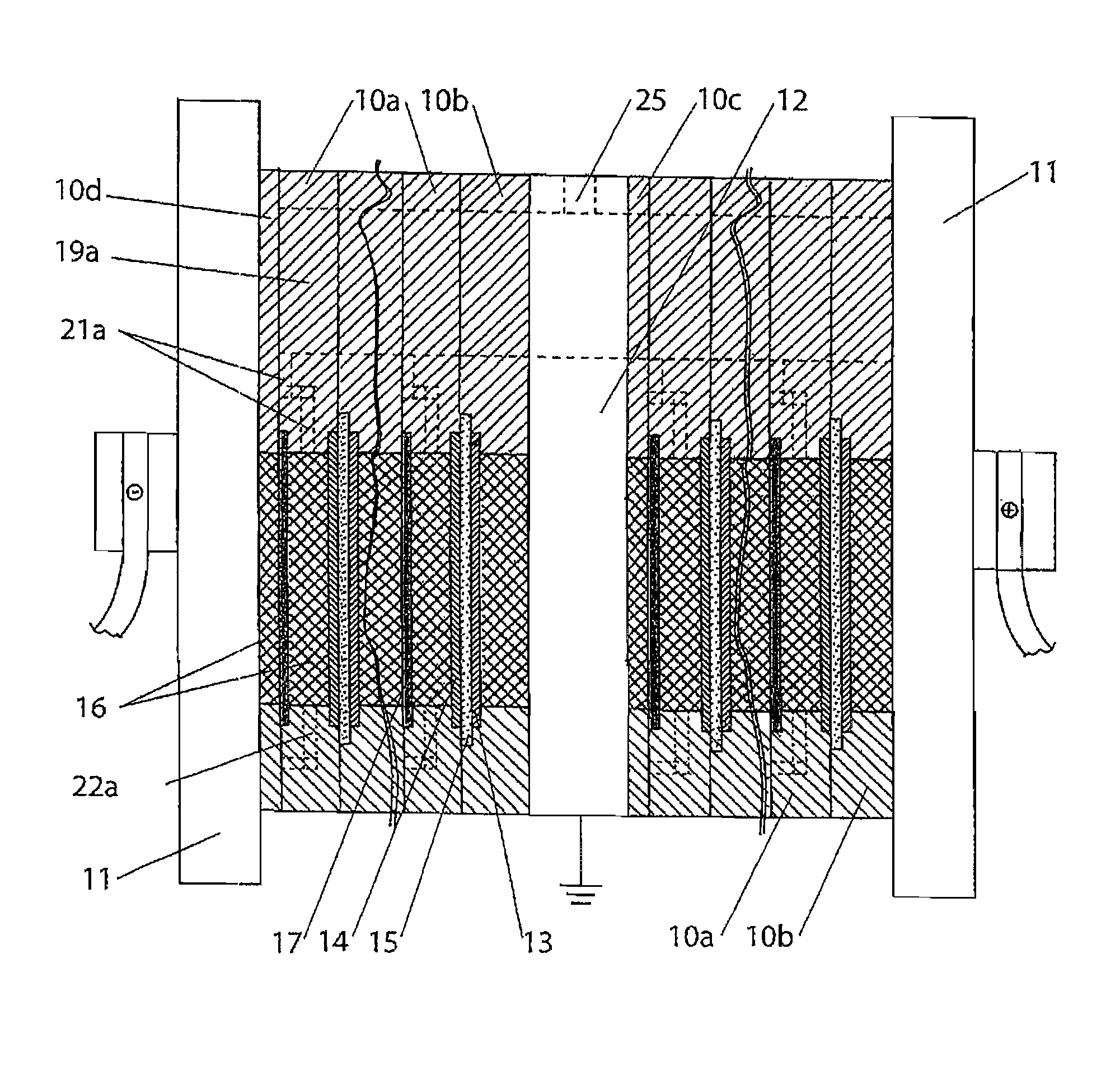
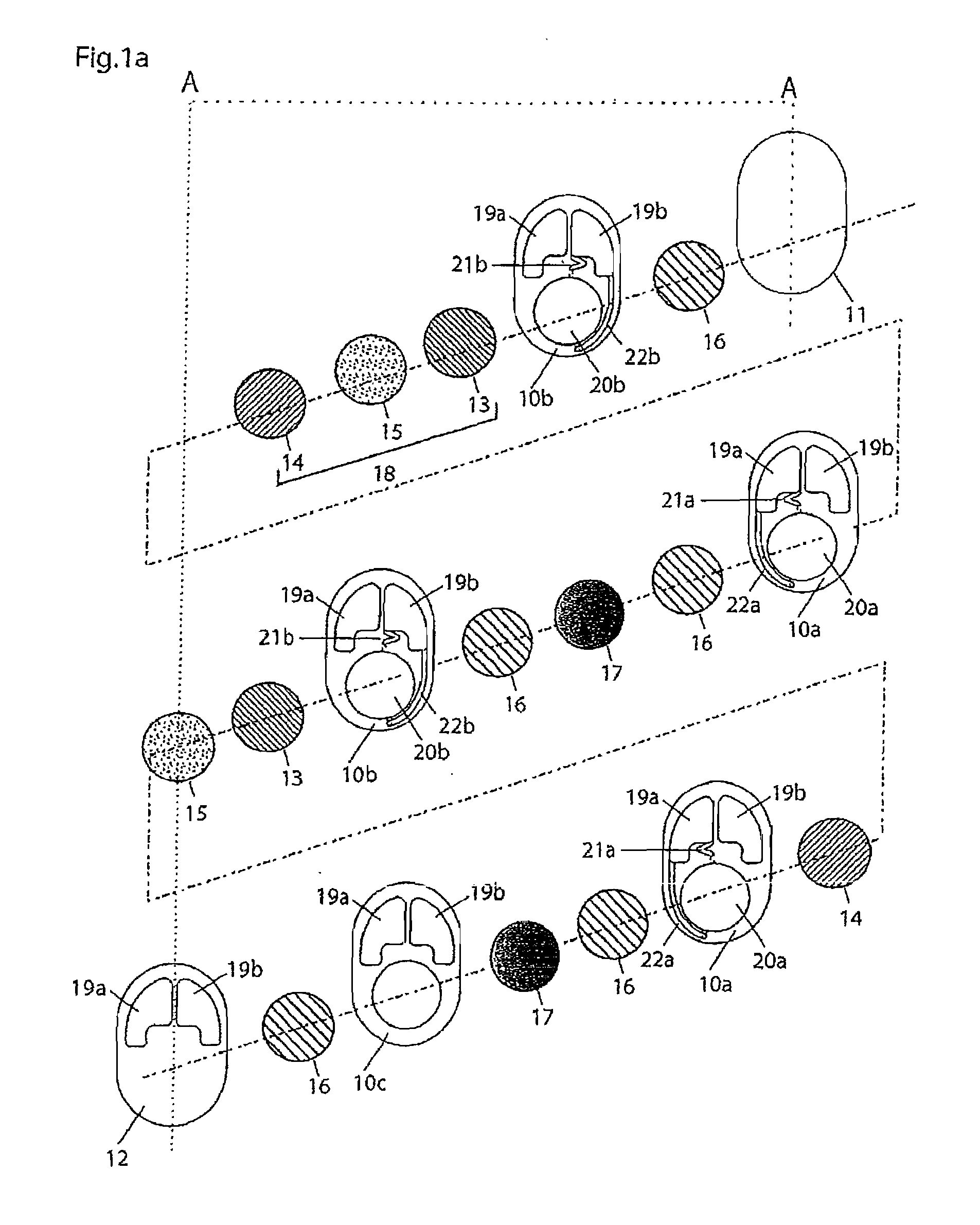
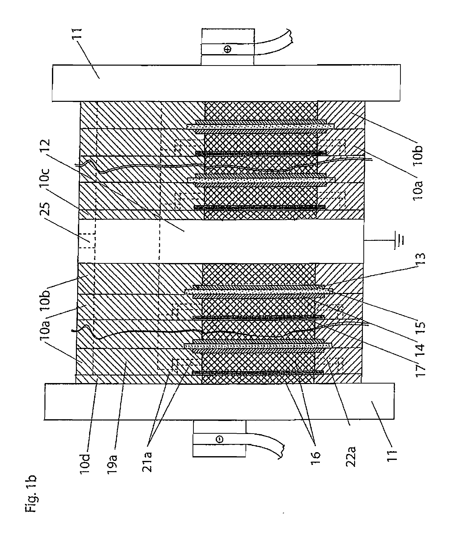
[0084]The fluid flows in a six-cell electrolyser module according to the present invention were modeled by computational fluid dynamics (CFD). For simplicity, the fluid flows on the hydrogen (cathodes) side only are described herein. The general structural plate configuration was as shown in FIG. 3, in which the gas-liquid passage 21 extends from the top part of half cell chamber opening 20 and partway under corresponding degassing chamber opening 19a, then doubles back over itself before joining the bottom part of degassing chamber opening 19a at the near side. The cell active area was 6,000 cm2. The hydrogen gas-liquid separation chamber was comprised of a main section 30 cm×50 cm×13.2 cm. The cross sectional area of the gas-liquid passages and the degassed liquid passages was 3 cm2. The maximum current density was 1,000 mA / cm2. This corresponds to a maximum hydrogen generation rate per half cell of 2.5 Nm3 / h, so the ratio of maximum hydrogen generation rate per half cell to the c...
example 2
[0085]Next, the number of cells in the electrolyser module of Example 1 was increased to 50 cells. The fluid flows in the 50-cell electrolyser module were modeled by CFD. For simplicity, the fluid flows on the hydrogen (cathodes) side only are described herein. The results for each half cell were similar to those obtained for half cells in the six-cell electrolyser module, demonstrating the inherent scalability of the design. For example, fluid flow rates in any of the degassed liquid passages in the 50-cell electrolyser module were within 6% of fluid flow rates in any of the degassed liquid passages in the six-cell electrolyser module. Furthermore: (i) fluid flow rates in degassed liquid passages were higher in the 50-cell electrolyser module than in the six-cell electrolyser module, and (ii) the fluid flow rates in the degassed liquid passages for each of the 50 cathode half cells were within 1% of each other. Similarly, void fractions at the tops of the 50 cathode half cell chamb...
example 3
[0086]Next, the number of cells in the electrolyser module of Example 2 was increased to 200 cells. The fluid flows in the 200-cell electrolyser module were modeled by CFD. For simplicity, the fluid flows on the hydrogen (cathodes) side only are described herein. The results for each half cell were similar to those obtained for half cells in six-cell and 50-cell electrolyser modules, demonstrating the inherent scalability of the design. For example, the range of fluid flow rates in the degassed liquid passages in the 200-cell electrolyser module was identical to the range of fluid flow rates in the degassed liquid passages in the 50-cell electrolyser module. Similarly, void fractions at the tops of the 200 cathode half cell chambers were almost equal, and also were almost equal to the void fractions at the tops of the cathode half cell chambers in the 50-cell electrolyser module.
[0087]The present electrolyser modules can be used in the production of various gases, for example chlori...
PUM
| Property | Measurement | Unit |
|---|---|---|
| Pressure | aaaaa | aaaaa |
| Length | aaaaa | aaaaa |
Abstract
Description
Claims
Application Information