Ion Guide Array

a technology of ion guide array and ion mobility spectrometer, which is applied in the direction of particle separator tube details, separation process, instruments, etc., can solve the problems of impractical commercial instruments with over 3 meters of drift tube length, lower resolution, and large diffusion loss, and achieve the effect of increasing the drift length of the preferred ion mobility spectrometer or separator, high resolution and low transmission cos

Active Publication Date: 2013-06-06
MICROMASS UK LTD
View PDF7 Cites 3 Cited by
  • Summary
  • Abstract
  • Description
  • Claims
  • Application Information

AI Technical Summary

Benefits of technology

[0047]One particular advantage of Electron Transfer Dissociation is that such a process is particularly suited for the identification of post-translational modifications (“PTMs”) since weakly bonded PTMs like phosphorylation or glycosylation will survive the electron induced fragmentation of the backbone of the amino acid chain.
[0092]According to an embodiment ions may be arranged to travel forwards or in a first direction through a first stacked ring ion guide or other ion guide before being transferred into a second stacked ring ion guide or other ion guide. The ions may then pass back through the second stacked ring ion guide or other ion guide in a second direction which is preferably opposed or counter to the first direction. The ions may then be transferred into a third stacked ring ion guide or other ion guide so that the ions then travel forwards through the third stacked ring ion guide or other ion guide in the first direction. It is contemplated that further stacked ring ion guides or other ion guides may also be provided so that ions may be passed between a plurality of stacked ring ion guides or other ion guides. In this fashion the drift distance or effective drift path length of the ions can be greatly increased without unduly lengthening the device. It will be appreciated that in a commercial mass spectrometer it is important to reduce the overall footprint and size of the instrument as much as possible.
[0115]According to the preferred embodiment the drift length of the preferred ion mobility spectrometer or separator is preferably increased by constraining ions into taking a tortuous path through the ion mobility spectrometer or separator. The overall physical dimensions of the preferred device are preferably considerably reduced when compared to a conventional ion mobility separator comprising a longitudinal drift tube having a comparable effective drift length.

Problems solved by technology

Operation at lower pressures more suitable for hybrid ion mobility-mass spectrometer instruments leads to greater diffusion losses and lower resolution.
However, the problem of the lower pressure of operation of mobility separation is that in order to achieve a high resolution of mobility separation, a relatively long drift tube must be employed in order to keep within the low field limit as described in more detail below.
To achieve a resolution of 100 under the same conditions would require a drift tube length of over 3 meters which is impractical for commercial instruments.

Method used


Image

  • Ion Guide Array
  • Ion Guide Array
  • Ion Guide Array

Examples


Embodiment Construction

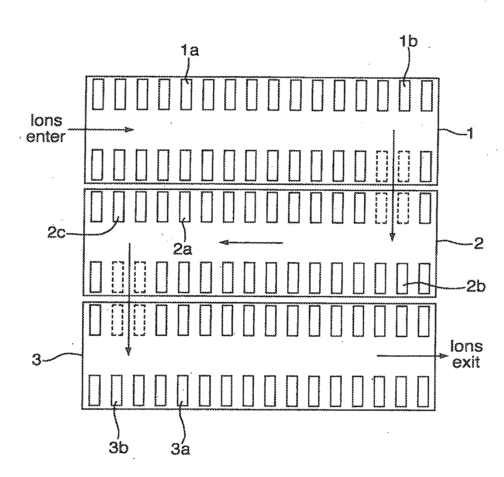
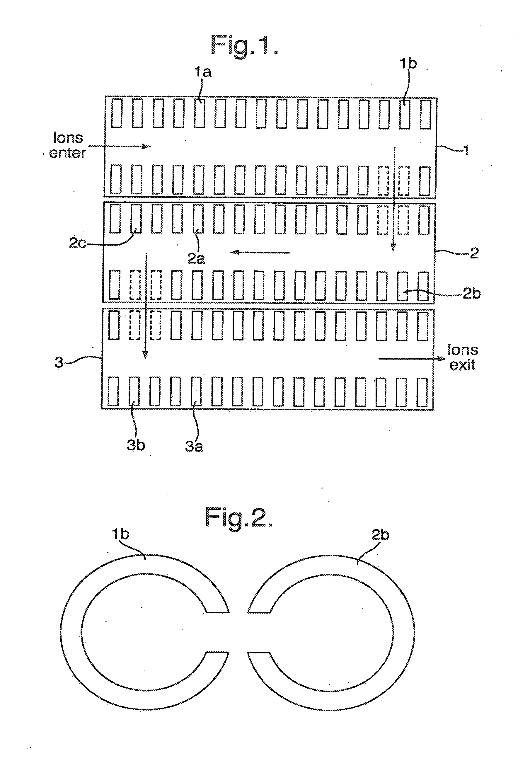
[0135]A preferred embodiment of the present invention will now be described with reference to FIG. 1. FIG. 1 shows an ion guide array comprising three stacked ring ion guides 1,2,3. Ions are arranged to enter a first stacked ring ion guide 1 comprising a plurality of ring electrodes a each having an aperture through which ions are transmitted. Ions are propelled along the length of the first ion guide 1 by applying a DC travelling wave or one or more transient DC voltages or potentials to the electrodes 1a comprising the first ion guide 1. Ions are therefore preferably translated to an end region of the first ion guide 1. A transfer section is preferably arranged at the end region of the first ion guide 1 and preferably comprises one or more ring electrodes 1b which have been modified so that a radial aperture or cut-out is provided in the ring electrodes 1b in the transfer section. In the particular example shown in FIG. 1 two ring electrodes 1b,2b in each stacked ring ion guide 1,...


PUM


Abstract

An ion guide array is disclosed comprising a first ion guide section and a second ion guide section. Each ion guide section may comprise a plurality of electrodes having an aperture through which ions are transmitted in use. A transfer section is arranged at the exit of the first ion guide section and ions are transmitted radially from the first ion guide section into the second ion guide section. Electrodes in the transfer section may have a radial aperture enabling ions to be transmitted radially from the first ion guide section to the second ion guide section.

Description

CROSS REFERENCE TO RELATED APPLICATIONS[0001]This application is a continuation of U.S. patent application Ser. No. 13 / 119,264 filed May 17, 2011, which is the National Stage of International Application No. PCT / GB2009 / 002232, filed Sep. 17, 2009 and designating the United States, which claims benefit of and priority to U.S. Provisional Patent Application No. 61 / 100,025, filed on Sep. 25, 2008 and United Kingdom Priority Application No. 0817115.9, filed Sep. 18, 2008. The contents of these applications are expressly incorporated herein by reference in their entirety.BACKGROUND OF THE INVENTION[0002]The present invention relates to an ion guide, an ion mobility spectrometer or separator, a mass spectrometer, a method of guiding ions, a method of separating ions according to their ion mobility and a method of mass spectrometry.[0003]The analytical utility of providing a forward impetus for ions confined by RF fields in the presence of gaseous media has long been understood. Particular...

Claims


Application Information

Patent Timeline
Patent Type & Authority Applications(United States)
IPC IPC(8): H01J49/02
CPCG01N27/622H01J49/062H01J49/02H01J49/065G01N27/623H01J49/063H01J49/40H01J49/408
Inventor HOYES, JOHN BRIANLANGRIDGE, DAVID J.
Owner MICROMASS UK LTD
Why Eureka
Try Eureka