Monocular stereoscopic imaging device

a stereoscopic imaging and monocular technology, applied in the field of monocular stereoscopic imaging devices, can solve problems such as uncomfortable feeling for photographers, and achieve the effects of enhancing visibility, and reducing an uncomfortable feeling of photographers

Active Publication Date: 2013-06-06
FUJIFILM CORP
View PDF1 Cites 18 Cited by
  • Summary
  • Abstract
  • Description
  • Claims
  • Application Information

AI Technical Summary

Benefits of technology

[0032]In the monocular stereoscopic imaging device according to the tenth aspect, when brightness of the left-eye image and the right-eye image is equal to or less than the predetermined value, that is, when the displayed three-dimensional image becomes dark, which deteriorates the visibility, the left-eye image and the right-eye image are synthesized so as to generate a two-dimensional image, and display this. Accordingly, it is possible to enhance the visibility. In addition, the stereoscopic effect becomes smaller in the two-dimensional image than in the three-dimensional image, thereby it is possible to reduce an uncomfortable feeling of the photographer due to the stereoscopic effect being increased.
[0033]According to the presently disclosed subject matter, it is possible to maintain, at a substantially constant level, the stereoscopic effect of the left-eye image and the right-eye image that are three-dimensionally displayed, even if the zoom lens is moved while photographing through images or moving images using the monocular 3D camera, thereby reducing an uncomfortable feeling of a photographer.

Problems solved by technology

Consequently, the zoom operation while photographing moving images or live view images (through images) may cause uncomfortable feeling to a photographer due to variation in stereoscopic effect.

Method used


Image

  • Monocular stereoscopic imaging device
  • Monocular stereoscopic imaging device
  • Monocular stereoscopic imaging device

Examples


first embodiment

[0058][Outline of Configuration of Imaging Device]

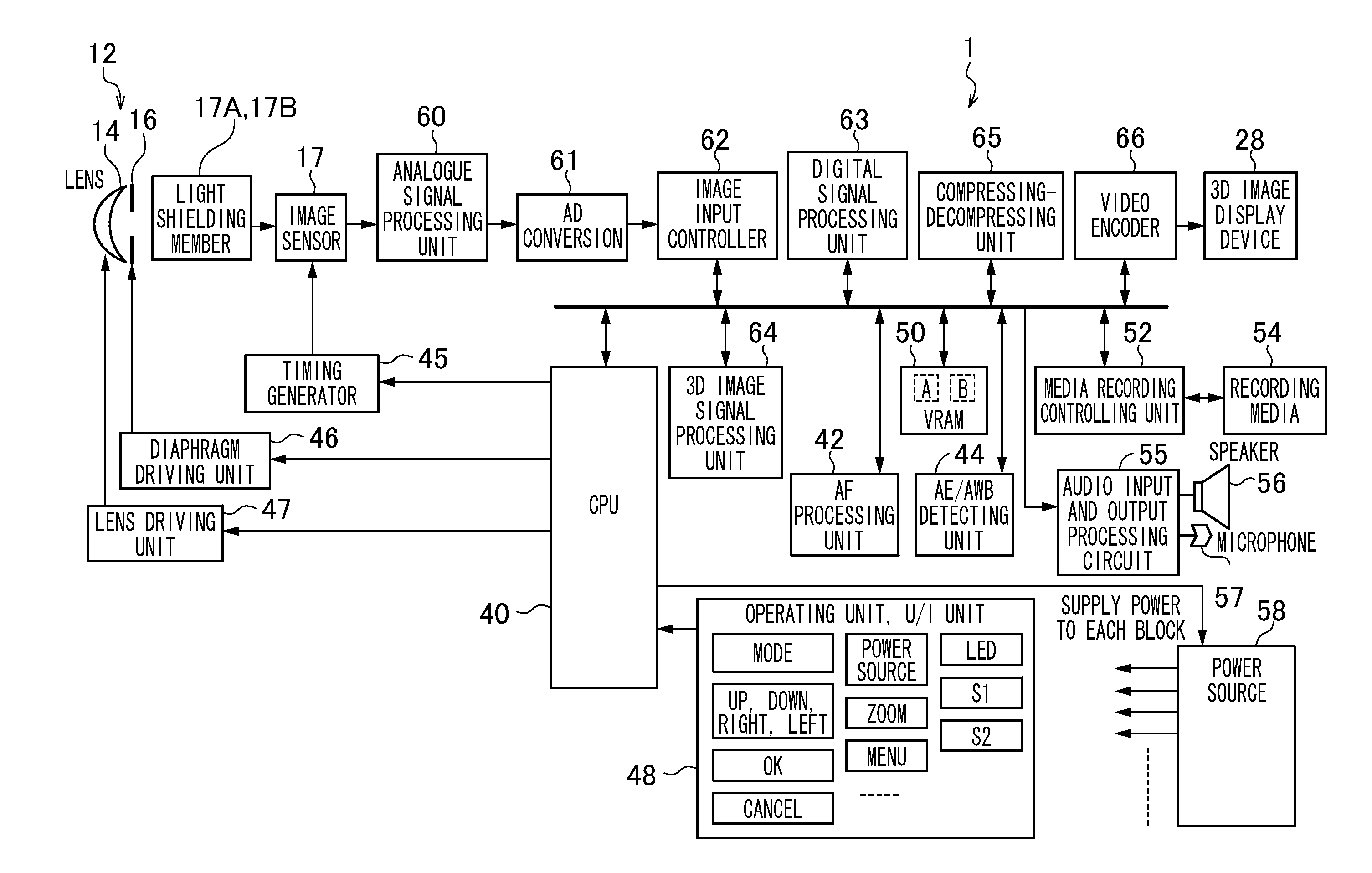
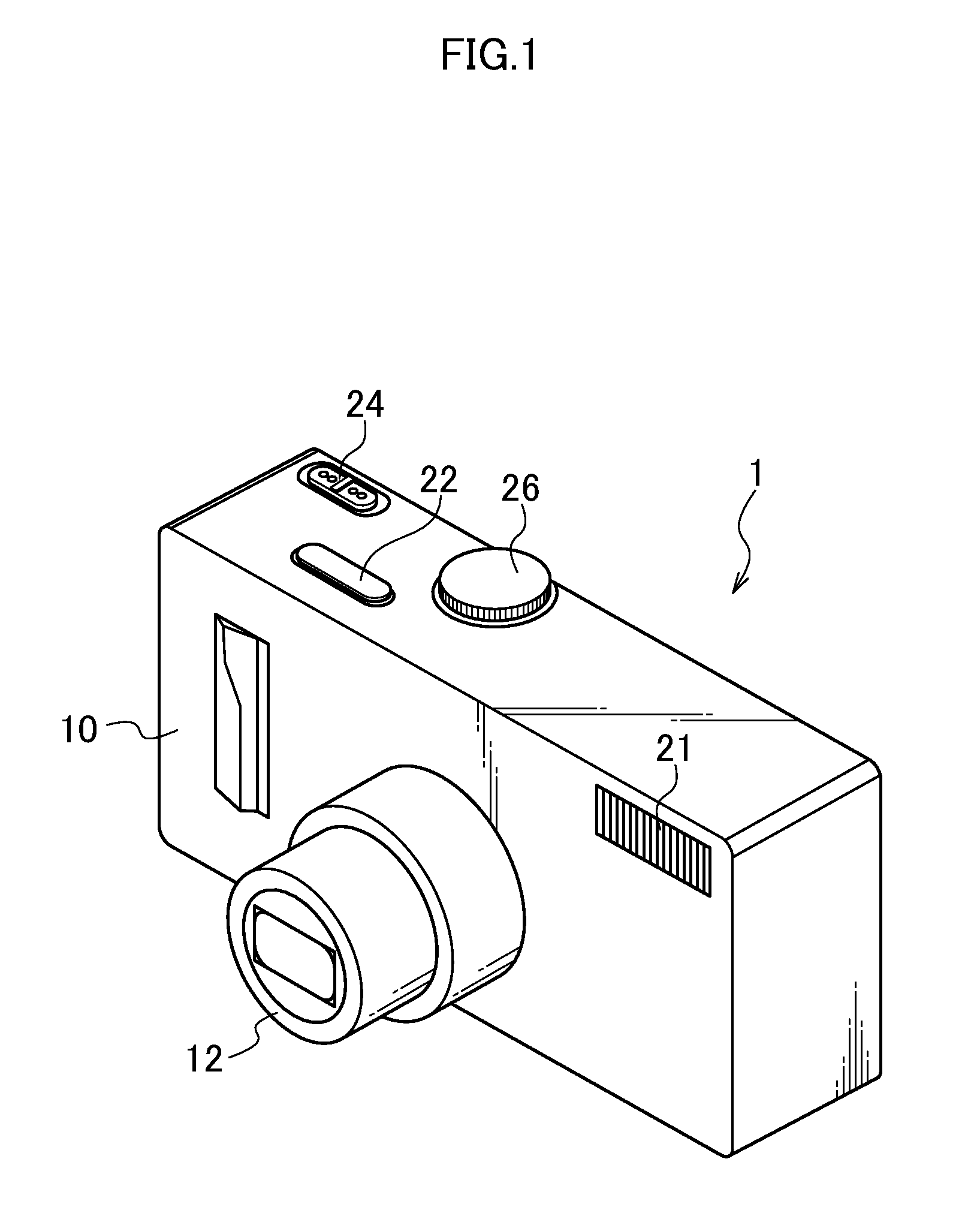
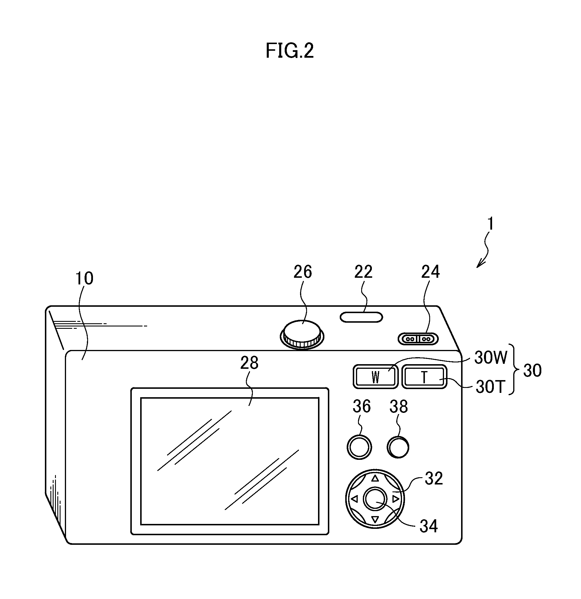
[0059]FIG. 1 is a front perspective view of a monocular stereoscopic imaging device 1 according to a first embodiment of the presently disclosed subject matter. FIG. 2 is a rear perspective view of the monocular stereoscopic imaging device 1. The monocular stereoscopic imaging device 1 is a digital camera for receiving light having passed through a lens on an image sensor, and converting the light into digital signals, and recording the signals on a storage media.

[0060]A camera body 10 of the monocular stereoscopic imaging device 1 is formed in a laterally long rectangular parallelopiped box shape. As illustrated in FIG. 1, a lens unit 12, a strobe 21, and other components are disposed on the front face of the camera body 10. A shutter button 22, a power / mode switch 24, a mode dial 26, and other components are disposed on the upper face of the camera body 10. In addition, as illustrated in FIG. 2, a liquid crystal monitor 28, a zoom ...

second embodiment

[0148]In the first embodiment of the presently disclosed subject matter, the stereoscopic effect of the three-dimensional image displayed on the liquid crystal monitor 28 is constantly maintained all the time even if the zoom lens is moved while displaying the live view images, however, the image displayed on the liquid crystal monitor 28 may become dark through the adjustment of the stereoscopic effect, which may deteriorate the visibility.

[0149]In a second embodiment of the presently disclosed subject matter, when the brightness of the displayed image, that is, the brightness of the photographed image becomes dark, the image is displayed as the 2D image, thereby reducing an uncomfortable feeling due to the displayed image being darkened. Hereinafter, description will be provided on a monocular stereoscopic imaging device 2 according to the second embodiment. The overall configuration of the imaging device is same as that of the first embodiment; therefore, description thereof will...

third embodiment

[0163]The variation of the first embodiment of the presently disclosed subject matter has been described by using the example in which the diaphragm 16′ whose aperture cannot be varied continuously, thereby the number of the driving steps of the diaphragm becomes smaller than the number of the driving steps of the zoom lens, and the slight variation of the stereoscopic effect is inevitable. In this case, the following operation is repetitively executed: when the zoom lens is moved in the telephoto direction (direction of increasing the focus distance), the aperture of the diaphragm is reduced by one stop before the zoom lens is moved, and thereafter the zoom lens is moved, so as to maintain the stereoscopic effect at a substantially constant level; however, the stereoscopic effect is varied while the zoom lens is moved because of two factors: (1) the variation of the stereoscopic effect due to variation of the incident light flux, and (2) the variation of the stereoscopic effect due...


PUM


Abstract

The monocular stereoscopic imaging device according to one aspect of the presently disclosed subject matter includes: an imaging optical system including a zoom lens and a diaphragm; a pupil dividing unit configured to divide a light flux having passed through a imaging optical system into multiple light fluxes; an imaging unit configured to receive the multiple light fluxes, so as to continuously acquire a left-eye image and a right-eye image; and a controlling unit configured to control a zoom lens driving unit to move the zoom lens in accordance with an instruction of changing the focus distance, and configured to control the diaphragm driving unit to maintain at a substantially constant level a stereoscopic effect of the left-eye image and the right-eye image three-dimensionally displayed on a display unit before and after the zoom lens is moved.

Description

CROSS-REFERENCE TO RELATED APPLICATIONS[0001]This application is a PCT Bypass continuation application and claims the priority benefit under 35 U.S.C. §120 of PCT Application No. PCT / JP2011 / 061804 filed on May 24, 2011 which application designates the U.S., and also claims the priority benefit under 35 U.S.C. §119 of Japanese Patent Application No. 2010-147891 filed on Jun. 29, 2010, which applications are all hereby incorporated by reference in their entireties.BACKGROUND OF THE INVENTION[0002]1. Field of the Invention[0003]The presently disclosed subject matter relates to a monocular stereoscopic imaging device, and more particularly to a technique for imaging each image of an object having passed through different areas in the right and left direction of a taking lens on an image sensor, so as to acquire an image for a left-eye and an image for a right-eye.[0004]2. Description of the Related Art[0005]Japanese Patent Application Laid-Open No. 10-042314 discloses a parallax image i...

Claims


Application Information

Patent Timeline
Patent Type & Authority Applications(United States)
IPC IPC(8): G03B35/00
CPCG03B9/02G03B35/08H04N13/0217G03B35/00H04N13/0235H04N13/0271H04N13/0296H04N13/0225H04N13/218H04N13/225H04N13/236H04N13/271H04N13/296
Inventor AWAZU, KOUHEIAOKI, TAKASHIENDO, HIROSHIHORII, HIROFUMI
Owner FUJIFILM CORP
Why Eureka
Try Eureka