Sound source separation device, sound source separation method and program

a separation device and sound source technology, applied in speech analysis, signal processing, ear treatment, etc., can solve the problems of excessive suppression of target sound, large difference in sound level of noise input to both microphones and phase difference thereof, and becoming musical noises, etc., to achieve the effect of suppressing a generation of musical noises

Inactive Publication Date: 2013-06-06
ASAHI KASEI KK
View PDF3 Cites 69 Cited by
  • Summary
  • Abstract
  • Description
  • Claims
  • Application Information

AI Technical Summary

Benefits of technology

[0017]It becomes possible to sufficiently suppress a generation of musical noises while maintaining the effect of Patent Document 1.

Problems solved by technology

As a result, the diffuse noises are irregularly sorted into sound source separation results, becoming musical noises.
However, when a microphone is placed at a remote location or when a microphone is molded on a casing of a cellular phone or a headset, etc., the difference in sound level of noises input to both microphones and the phase difference thereof become large.
Hence, if the gain obtained from the one microphone is directly applied to another microphone, the target sound may be excessively suppressed for each band, or noises may remain largely.
As a result, it becomes difficult to sufficiently suppress a generation of musical noises.

Method used


Image

  • Sound source separation device, sound source separation method and program
  • Sound source separation device, sound source separation method and program
  • Sound source separation device, sound source separation method and program

Examples


first embodiment

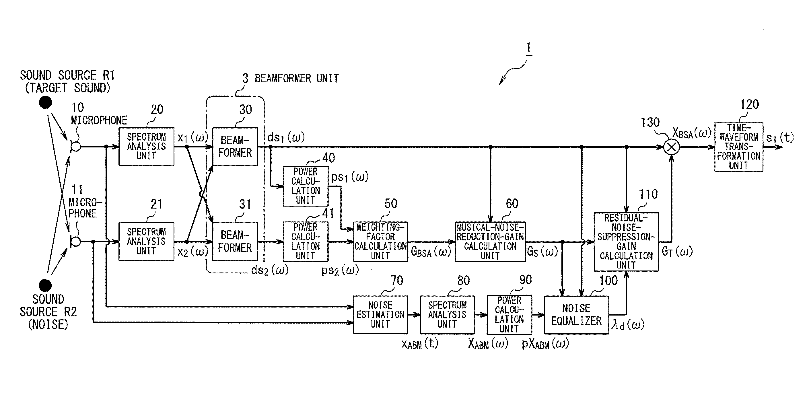
[0045]FIG. 1 is a diagram showing a basic configuration of a sound source separation system according to a first embodiment. This system includes two micro-phones (hereinafter, referred to as “microphones”) 10 and 11, and a sound source separation device 1. The explanation will be given below for the embodiment in which the number of the microphones is two, but the number of the microphones is not limited to two as long as at least equal to or greater than two microphones are provided.

[0046]The sound source separation device 1 includes hardware, not illustrated, such as a CPU which controls the whole sound source separation device and which executes arithmetic processing, a ROM, a RAM, and a storage device like a hard disk device, and also software, not illustrated, including a program and data, etc., stored in the storage device. Respective functional blocks of the sound source separation device 1 are realized by those hardware and software.

[0047]The two microphones 10 and 11 are p...

second embodiment

[0109]FIG. 9 is a diagram showing a basic configuration of a sound source separation system according to a second embodiment of the present invention. The feature of the sound source separation system of this embodiment is to include a control unit 160. The control unit 160 controls respective internal parameters of the noise estimation unit 70, the noise equalizer 100, and the residual-noise-suppression-gain calculation unit 110 based on the weighting factor GBSA(ω) across the entire frequency band. Example internal parameters are a step size of the adaptive filter, a spectrum floor value β of the weighting factor GBSA(ω), and a noise quantity of estimated noises.

[0110]More specifically, the control unit 160 executes following processes. For example, an average value of the weighting factor GBSA(ω) across the entire frequency band is calculated. If such an average value is large, it is possible to make a determination that a sound presence probability is high, so that the control u...

third embodiment

[0117](First Configuration)

[0118]FIG. 11 shows an illustrative basic configuration of a sound source separation system according to a third embodiment of the present invention.

[0119]A sound source separation device 1 of the sound source separation system shown in FIG. 11 includes a spectrum analyze units 20 and 21, beamformers 30 and 31, power calculation units 40 and 41, a weighting-factor calculation unit 50, a weighting-factor multiplication unit 310, and a time-waveform transformation unit 120. The configuration other than the weighting-factor multiplication unit 310 is consistent with the configurations of the above-explained other embodiments.

[0120]The weighting-factor multiplication unit 310 multiplies a signal ds1(ω) obtained by the beamformer 30 by a weighting factor calculated by the weighting-factor calculation unit 50.

[0121](Second Configuration)

[0122]FIG. 12 is a diagram showing another illustrative basic configuration of a sound source separation system according to th...


PUM


Abstract

With conventional source separator devices, specific frequency bands are significantly reduced in environments where dispersed static is present that does not come from a particular direction, and as a result, the dispersed static may be filtered irregularly without regard to sound source separation results, giving rise to musical noise. In an embodiment of the present invention, by computing weighting coefficients which are in a complex conjugate relation, for post-spectrum analysis output signals from microphones (10, 11), a beam former unit (3) of a sound source separator device (1) thus carries out a beam former process for attenuating each sound source signal that comes from a region wherein the general direction of a target sound source is included and a region opposite to said region, in a plane that intersects a line segment that joins the two microphones (10, 11). A weighting coefficient computation unit (50) computes a weighting coefficient on the basis of the difference between power spectrum information calculated by power calculation units (40, 41).

Description

TECHNICAL FIELD[0001]The present invention relates to a sound source separation device, a sound source separation method, and a program which use a plurality of microphones and which separate, from signals having a plurality of acoustic signals mixed, such as a plurality of voice signals output by a plurality of sound sources, and various environmental noises, a sound source signal arrived from a target sound source.BACKGROUND ART[0002]When it is desired to record particular voice signals in various environments, the surrounding environment has various noise sources, and it is difficult to record only the signals of a target sound through a microphone. Accordingly, some noise reduction process or sound source separation process is necessary.[0003]An example environment that especially needs those processes is an automobile environment. In an automobile environment, because of the popularization of cellular phones, it becomes typical to use a microphone placed distantly in the automo...

Claims


Application Information

Patent Timeline
Patent Type & Authority Applications(United States)
IPC IPC(8): G10K11/178H04R29/00H04R3/00G10L21/0208G10L21/0216G10L21/0224G10L21/0232G10L21/028
CPCG10L21/028G10L2021/02166G10K11/178H04R3/00H04R3/005H04R2430/20H04R2499/13G10L21/0232H04R29/005G10L21/02
Inventor MATSUI, SHINYAISHIKAWA, YOJINAGAHAMA, KATSUMASA
Owner ASAHI KASEI KK
Why Eureka
Try Eureka