Systems and methods for photonic polarization-separating apparatuses for optical network applications

a technology of optical network and separation apparatus, applied in the field of system and method of photonic polarization separation apparatus for optical network application, can solve the problems of inconvenient use of silicon for light emission or optical amplification, preventing the fabrication of monolithically integrated opto-electronic integrated circuits on silicon, and limiting the integration of advanced electrical functions on silicon to niche, high-performance applications

Active Publication Date: 2013-06-06
SKORPIOS TECH
View PDF18 Cites 31 Cited by
  • Summary
  • Abstract
  • Description
  • Claims
  • Application Information

AI Technical Summary

Benefits of technology

[0021]Numerous benefits are achieved by way of the present invention over conventional techniques. For example, embodiments of the present invention provide methods and systems for rotating optical polarization in optoelectronics. The capability to rotate polarization enables monolithic integration of polarization diversity receivers in coherent optical receivers or in systems using polarization multiplexing. For example, through the use of a 90-degree rotator, TE-polarized light can be converted to TM-polarization, and vice versa. This allows the use of a local oscillator (LO) emitting in a single polarization state for the receiver. Monolithic integration allows careful control of path lengths and propagation losses to ensure that power balance and phase relationships are maintained in applications such as balanced receivers. Furthermore, the use of a combination of 45-degree reciprocal and non-reciprocal rotators allows the implementation of devices such as isolators on a single substrate. This is of importance for future generations of low-cost photonic-electronic packages that may have reflective interfaces that would otherwise destabilize the operation of the chip.

Problems solved by technology

Silicon has not been useful for light emission or optical amplification due to its indirect energy bandgap.
This deficiency has prevented the fabrication of monolithically integrated opto-electronic integrated circuits on silicon.
At the same time, integration of advanced electrical functions on these materials has been limited to niche, high-performance applications due to the much higher cost of fabricating devices and circuits in these materials.

Method used


Image

  • Systems and methods for photonic polarization-separating apparatuses for optical network applications
  • Systems and methods for photonic polarization-separating apparatuses for optical network applications
  • Systems and methods for photonic polarization-separating apparatuses for optical network applications

Examples


Embodiment Construction

[0037]Photonic polarization beam splitters integrated on silicon are preferable for the commercial deployment of optoelectronic integrated circuits. Silicon is a preferable material for electronic integration. Silicon technology has advanced such that extremely complex electronic functions can be realized very inexpensively. Embodiments of the present invention relate to systems and methods for integrated photonic polarization beam splitters.

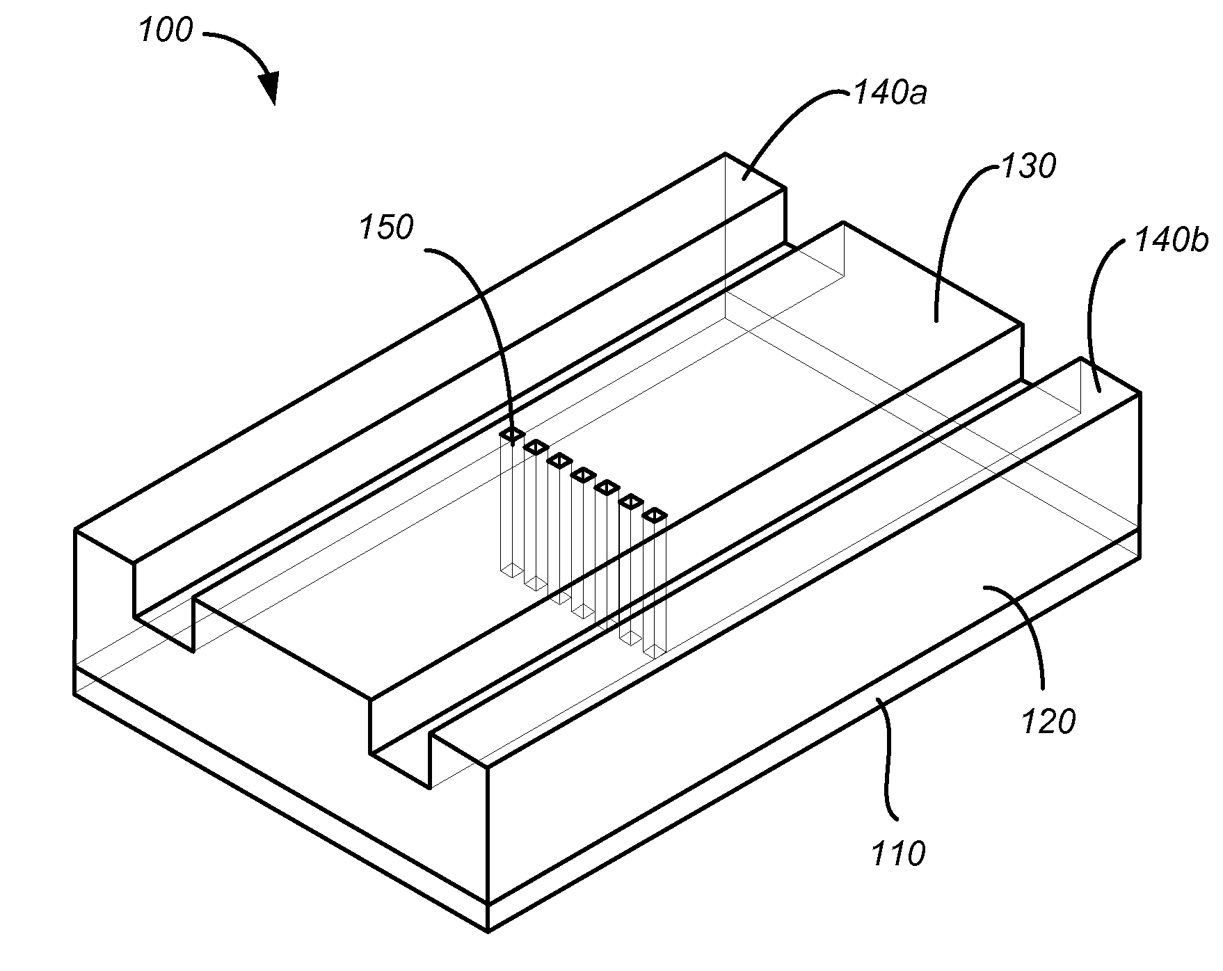
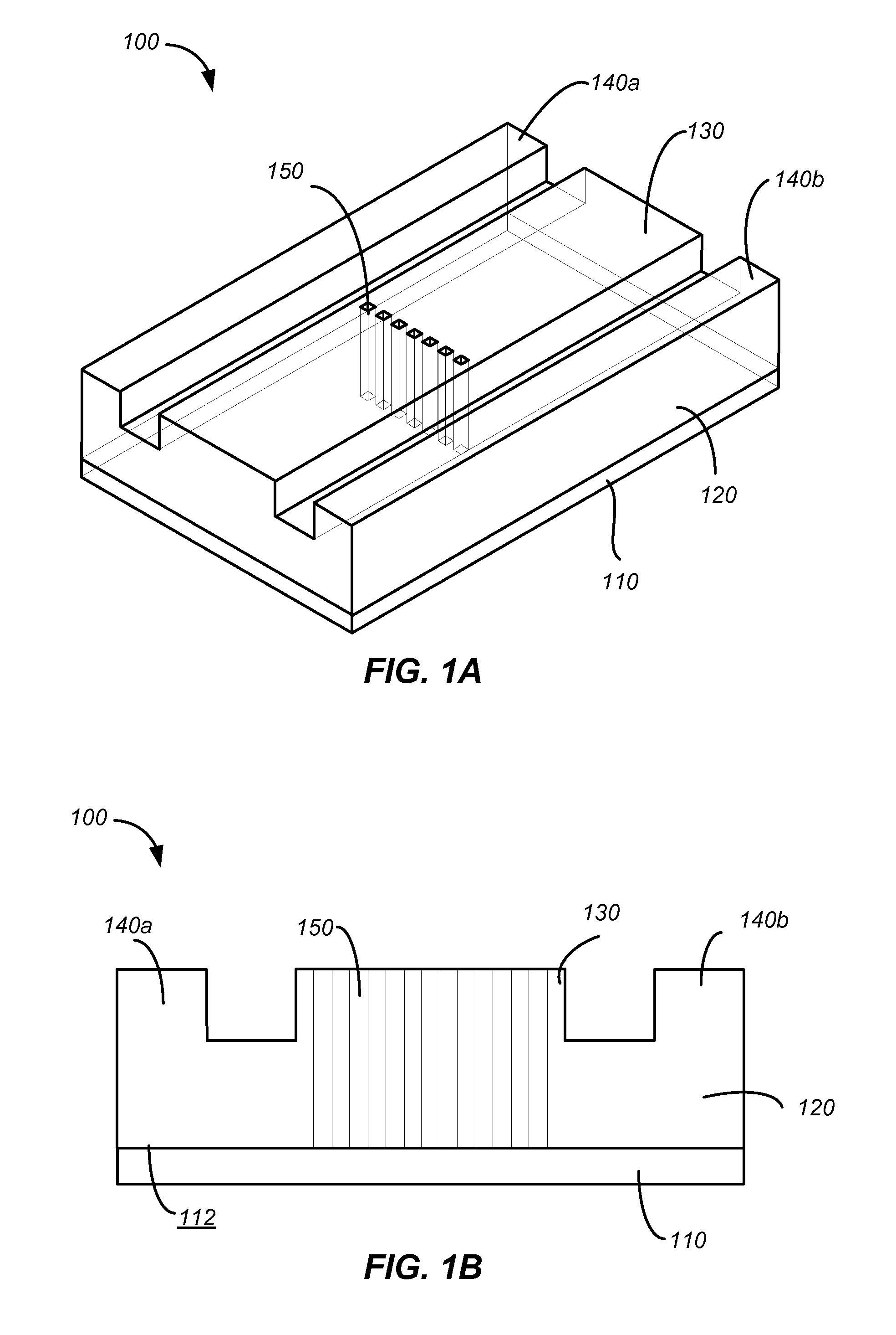
[0038]FIGS. 1A and 1B are a perspective view and a cross-sectional view, respectively, of a simplified schematic diagram illustrating a waveguide polarizer 100 including an array of embedded structures 150 according to an embodiment of the invention. The waveguide polarizer 100 includes a substrate 110 having a surface 112, and a waveguide 120 coupled to the surface 112 of the substrate 110. The waveguide 120 includes a beam propagation portion 130, and two side portions 140a and 140b flanking the beam propagation portion 130. The waveguide pola...


PUM


Abstract

An integrated photonic polarization-separating apparatus includes a first waveguide polarization beam splitter (PBS) having a first port, a second port, a third port, and a fourth port and a first polarization rotator optically coupled to the first port of the first waveguide PBS. The apparatus also includes a first Faraday rotator optically coupled to the first polarization rotator and a second polarization rotator optically coupled to the second port of the first waveguide PBS. The apparatus further includes a second Faraday rotator optically coupled to the second polarization rotator and a second waveguide PBS having a first port, a second port, a third port, and a fourth port. The third port is optically coupled to the first Faraday rotator and the fourth port is optically coupled to the second Faraday rotator.

Description

CROSS-REFERENCES TO RELATED APPLICATIONS[0001]This application claims the benefit under 35 U.S.C. §119(e) of U.S. Provisional Patent Application No. 61 / 494,871, filed on Jun. 8, 2011, entitled “Method and System for Silicon Photonic Polarization Control,” the disclosure of which is hereby incorporated by reference in its entirety for all purposes.[0002]The following three U.S. patent applications (including the present application) are being filed concurrently, and the entire disclosure of the other applications are incorporated by reference into this application for all purposes:[0003]Application Ser. No. ______, filed Jun. 7, 2012, entitled “SYSTEMS AND METHODS FOR PHOTONIC POLARIZATION BEAM SPLITTERS” (Attorney Docket No. 92970-808288(000510US));[0004]Application Ser. No. ______, filed Jun. 7, 2012, entitled “SYSTEMS AND METHODS FOR PHOTONIC POLARIZATION ROTATORS” (Attorney Docket No. 92970-837395(000520US)); and[0005]Application Ser. No. ______, filed Jun. 7, 2012, entitled “SYS...

Claims


Application Information

Patent Timeline
Patent Type & Authority Applications(United States)
IPC IPC(8): G02B6/26
CPCG02B6/26G02B6/126G02B5/3058G02B6/105G02F1/0036G02F1/093G02B6/2726G02B6/2746G02B6/2766G02B2006/12061
Inventor DALLESASSE, JOHNKRASULICK, STEPHEN B.
Owner SKORPIOS TECH
Why Eureka
Try Eureka