Image forming apparatus

a color image and forming apparatus technology, applied in the field of electrographic photography color image forming apparatus, can solve the problems of affecting the direction of the optical path of the laser beam, taking the required time for calibration to form a pattern image, and it is difficult to identify these points, so as to reduce misregistration

Inactive Publication Date: 2013-06-06
CANON KK
View PDF6 Cites 4 Cited by
  • Summary
  • Abstract
  • Description
  • Claims
  • Application Information

AI Technical Summary

Benefits of technology

[0010]Another object of the present invention is to form a pattern image for correcting misregistration between pages without widening page intervals, performs a misregistration correction process, and reduces misregistration caused by variation in laser irradiation position due to variation in temperature. A further object of the present invention is to provide an image forming apparatus, including a plurality of image forming devices including a developing device that develops an electrostatic latent image formed on an image bearing member to form a toner image, and a transferring device that transfers the toner image developed by the developing device onto any of a conveyance member and a transfer material on the conveyance member, for each of a plurality of colors, an exposure unit irradiating the image bearing member with a laser beam to form the electrostatic latent image on the image bearing member, a detector detecting a toner image for detection that is a toner image for detecting a positional deviation of each color transferred onto the conveyance member by the transferring device, and a control device detecting and correcting the positional deviation of each color based on a detection result of the toner image for detection detected by the detector, wherein the control device allows one of said plurality of image forming devices to form a toner image for detection with one color between pages in a print job including plural pages of images, and corrects timing at which the exposure unit emits the laser beam based on a time between timing pertaining to start of forming the toner image for detection and timing on which the detector detects the toner image for detection.

Problems solved by technology

Rise in temperature due to operation of the image forming apparatus thermally deforms the frame, and thus changes the orientations of these elements, thereby affecting the direction of the optical path of the laser beam.
However, this method takes required time for calibration to form a pattern image.
In such a case, it can be considered that relative temperature balance at multiple points complexly deforms an optical unit, which, in turn, varies laser irradiation position.
However, it is difficult to identify these points.
However, in an image forming apparatus having a configuration where one optical unit can scan multiple laser beams for realizing reduction in size and cost of the image forming apparatus, the optical unit has a complicated structure.
In an aspect, according to increase in unit packaging density in the apparatus due to reduction in size, thermal effects on the optical unit affected from the periphery become complicated.
Owing to the effects of these factors, it is difficult to find correlation between tendency of variation in misregistration and variation in temperature around the optical unit.
That is, there is a possibility that variation in laser irradiation position according to variation in temperature cannot be estimated.
However, if a multi-color toner image is formed between pages, a sufficient number of pattern images cannot be accommodated in prescribed page intervals.
This method unfortunately decreases throughput.

Method used


Image

  • Image forming apparatus
  • Image forming apparatus
  • Image forming apparatus

Examples


embodiment 1

[0024][Configuration of Image Forming Apparatus]

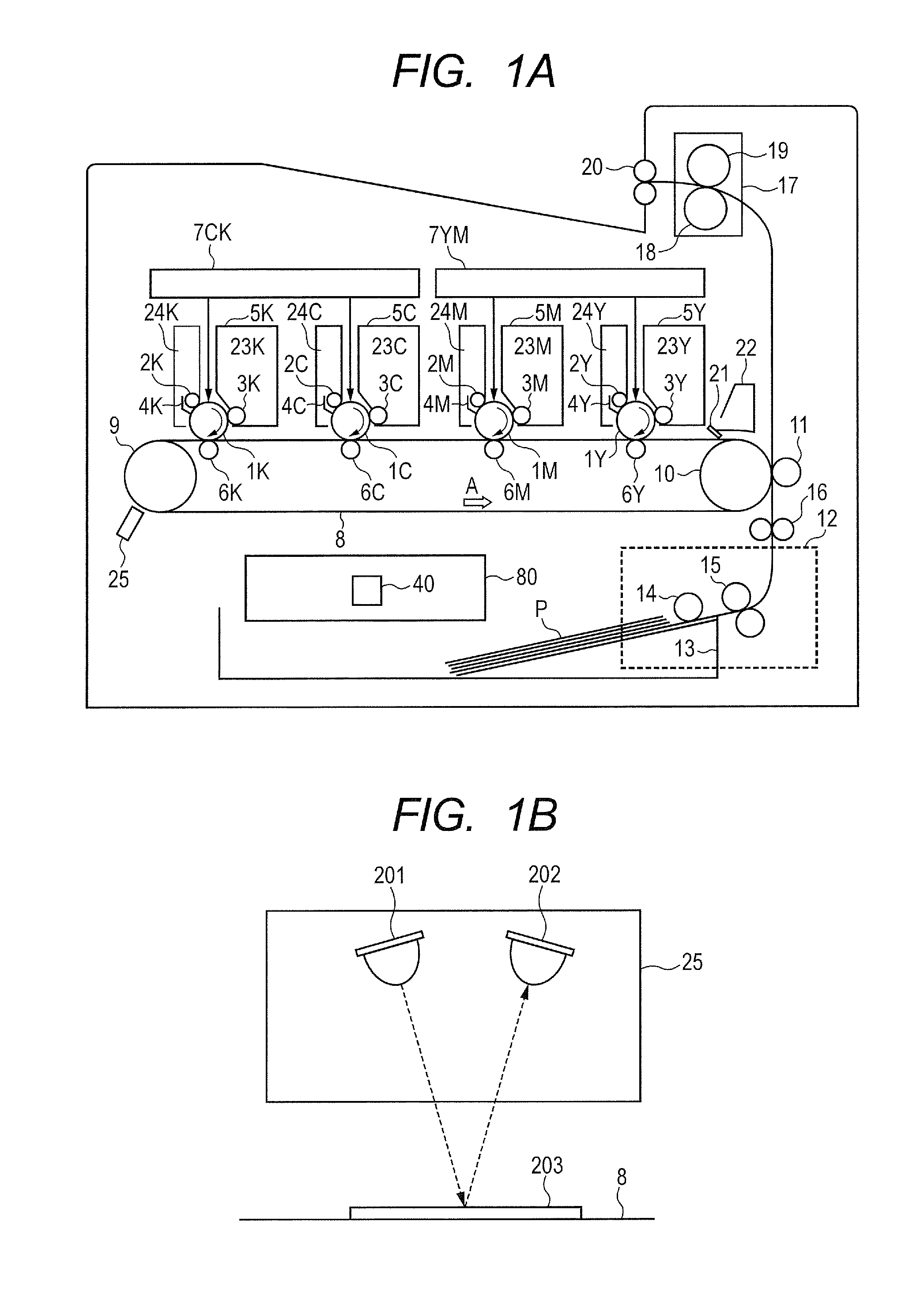
[0025]A color image forming apparatus (hereinafter, called a main body) illustrated in FIG. 1A includes process cartridges 5Y, 5M, 5C and 5K detachably attached to a main body. These four process cartridges 5Y, 5M, 5C and 5K have the same configuration, but are different in color, i.e., in forming images of yellow (Y), magenta (M), cyan (C) and black (K) toner. Hereinafter, except for description on a specific color, symbols of Y, M, C and K are omitted. A process cartridge 5 includes a toner container 23, a photosensitive drum 1 that is an image bearing member, a charging roller 2, a developing roller 3, a drum cleaning blade 4 and a waste toner container 24. Laser units 7YM and 7CK (exposure unit) are arranged above the process cartridge 5. The laser unit 7YM performs exposure based on an image signal onto photosensitive drums 1Y and 1M. The laser unit 7CK performs exposure based on an image signal onto photosensitive drums 1C and 1K...

embodiment 2

[0053][Problem of Intermittent Printing]

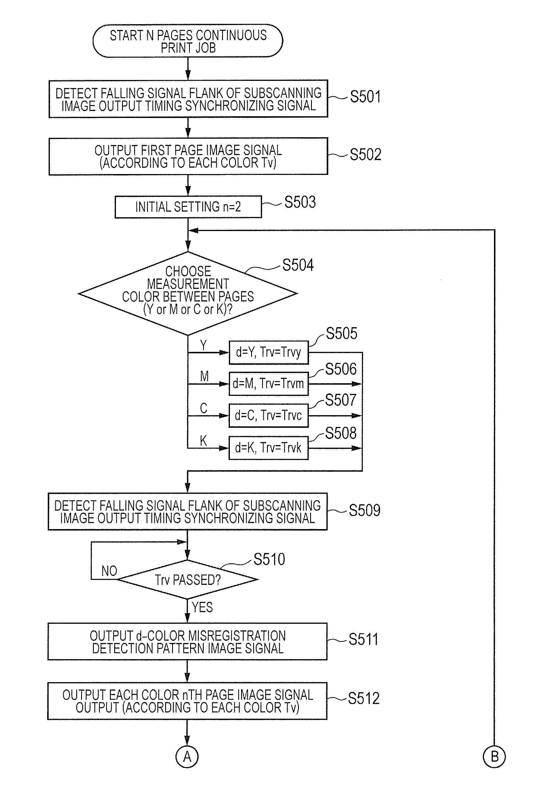
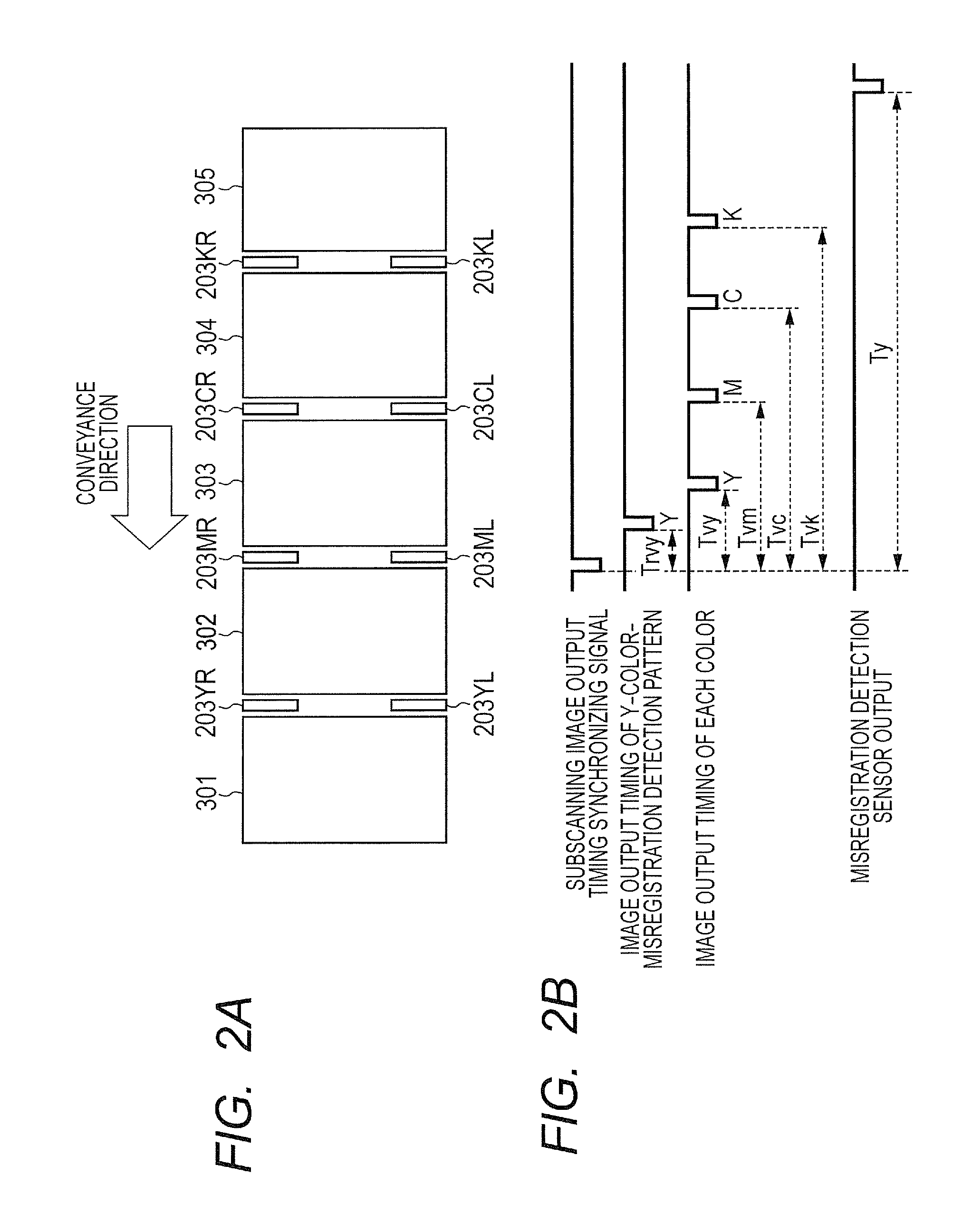
[0054]The method of detecting and correcting misregistration between pages in Embodiment 1 adopts one color as the reference color, regards the colors other than the one color as object colors, calculates the relative amount of misregistration with reference to the reference color, and is applicable in the case of a continuous print job for at least three pages. Accordingly, in a continuous printing for two pages, Ty for only one color is measured, and the relative amount of misregistration between the reference color and the object color cannot be calculated. Thus, in the case of a continuous print job for only two pages, the misregistration detection pattern with the reference color may be formed and measured, and the misregistration detection pattern with the object color may be formed on and after the second page in the multi-page continuous print job and measured. However, there is a possibility that a thermal shift occurs between the con...

embodiment 3

[0072]The method of detecting and correcting misregistration between pages in Embodiment 2 performs the correction reference determination sequence. Thus, the detection and correction of the misregistration cannot be performed in the correction reference determination sequence. Accordingly, there is a possibility that misregistration occurs in an image-writing in the correction reference determination sequence. To address thereto, it can be considered that any correction reference time Tx can be preliminarily determined without executing the correction reference determination sequence. In the case of thus determining any correction reference time Tx, detection and correction of the misregistration can be performed from the first page. However, with certain variation in color, there is a possibility that the misregistration cannot be reduced instead. This embodiment will describe a configuration that determines the correction reference time Tx and detects and corrects the misregistra...


PUM


Abstract

The image forming apparatus includes a plurality of image forming devices that includes a developing device and a transferring device, an exposure unit irradiating the image bearing member with a laser beam, a detector detecting a toner image for detection, and a CPU for detecting and correcting the positional deviation of each color, wherein the CPU forms the toner image for detection on a color-by-color basis between pages in a print job including plural pages of images, and corrects times Trv and Tv from timing on which a subscanning image-writing timing synchronizing signal is output to timing on which a laser unit emits a laser beam based on times Ty to Tk between timing on which the subscanning image-writing timing synchronizing signal is output and timing on which the color misregistration detection sensor detects the misregistration detection pattern.

Description

BACKGROUND OF THE INVENTION[0001]1. Field of the Invention[0002]The present invention relates to electronic photography color image forming apparatuses, such as a laser printer, a copier and a facsimile, which include a plurality of photosensitive members.[0003]2. Description of the Related Art[0004]In an image forming apparatus that overlaps multi-color toner images with each other to form a color image, it is important that each color is correctly printed on a prescribed position on a printed matter, i.e., misregistration does not occur in view of quality of products. Hereinafter, “misregistration” is defined as misragistaratio regarding colors. There may be various factors of misregistration. Among major factors of adverse effects, there is a factor of variation in laser irradiation position on a photosensitive member caused according to thermal deformation of an optical unit. Typically, the optical unit has a configuration that causes a rotating polygon mirror to reflect a laser...

Claims


Application Information

Patent Timeline
Patent Type & Authority Applications(United States)
IPC IPC(8): G03G15/01
CPCG03G15/01G03G2215/0158G03G15/5058G03G15/0189
Inventor ITOH, MASATOSHI
Owner CANON KK
Why Eureka
Try Eureka