Head Replaceable Cutting Tool

a cutting tool and head technology, applied in the field of cutting tools, can solve the problems of deformation of the clamp screw, failure to accurately, and inability to provide the constant final position of the cutting edge portion,

Inactive Publication Date: 2013-06-06
TAEGUTEC
View PDF5 Cites 20 Cited by
  • Summary
  • Abstract
  • Description
  • Claims
  • Application Information

AI Technical Summary

Benefits of technology

[0007]The present disclosure provides embodiments of a cutting tool wherein a cutting head is replaceably coupled to a shank as well as embodiments of a cutting head and a shank. Embodiments of the cutting tool disclosed herein provide screw-engagement between a cutting head and a shank without the use of va

Problems solved by technology

This may cause a deformation of the clamp screw and fail to accurately position the cutting head to the shank in a predetermined position.
This does not provide the constant final posi

Method used


Image

  • Head Replaceable Cutting Tool
  • Head Replaceable Cutting Tool
  • Head Replaceable Cutting Tool

Examples


Embodiment Construction

[0021]A detailed description may be provided with reference to the accompanying drawings. One of ordinary skill in the art may realize that the following description is illustrative only and is not in any way limiting. Other embodiments may readily suggest themselves to such skilled persons having the benefit of this disclosure.

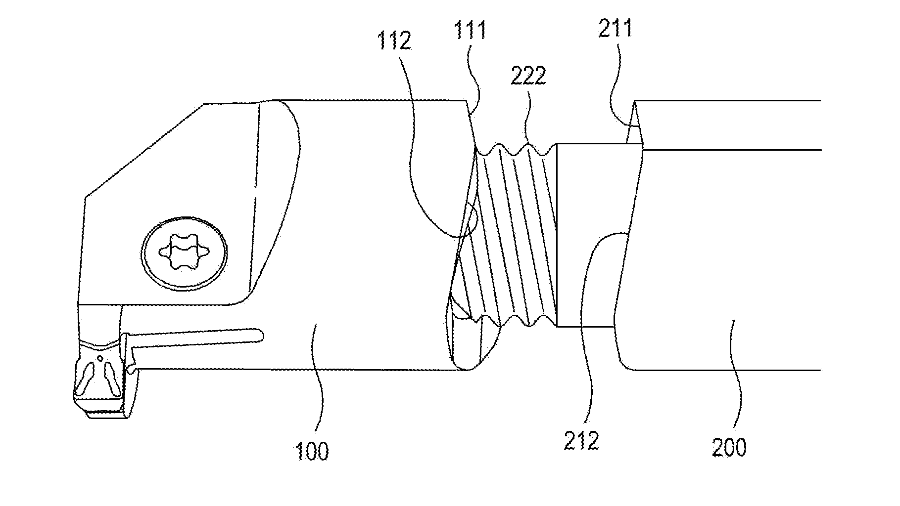
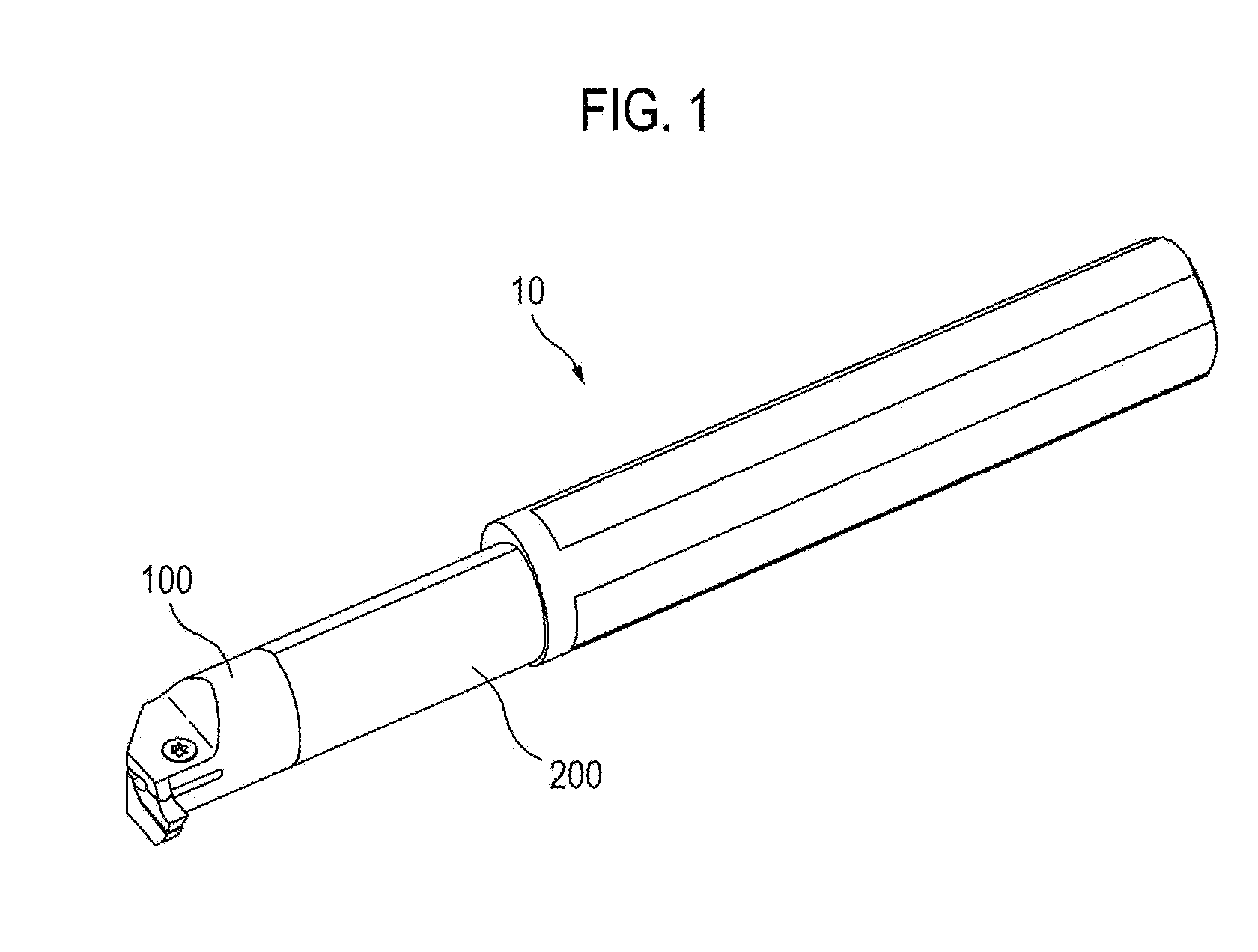
[0022]FIG. 1 schematically shows a cutting tool 10 according to one embodiment wherein a replaceable cutting head 100 is coupled to a shank 200.

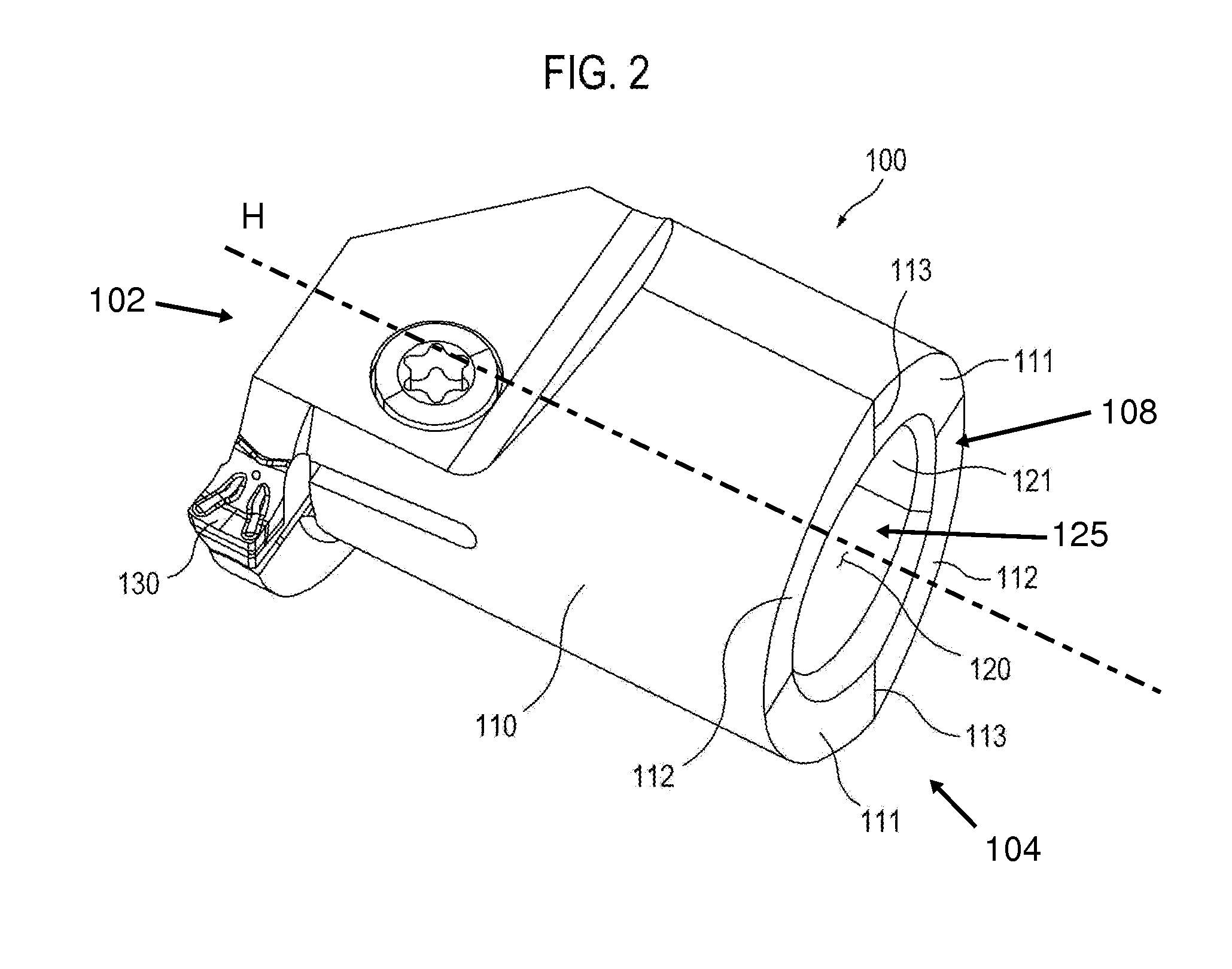
[0023]FIG. 2 shows a cutting head 100 according to one embodiment. The cutting head 100 includes a body 110 having a head forward end 102 and a head rear end 104. The body 110 extends along a head axis H in the same axial direction as a shank axis S of the shank when the cutting head is coupled to the shank. The body 110 may have a cylindrical shape, an elliptic cylindrical shape or any shape in accordance with a shape of the shank 200. The body 110 may have a key way which a spanner engages when the cutting head 100 ...


PUM

PropertyMeasurementUnit
Pressureaaaaaaaaaa

Abstract

A cutting tool has a cutting head and a shank. The cutting head has a body, a head threaded portion, a first helical head surface and a second helical head surface. The shank has a cylindrical portion, a shank threaded portion, a first helical contact surface and a second helical contact surface. The head threaded portion screw-engages the shank threaded portion. The first helical head surface is parallel to the thread of the head threaded portion and the first helical contact surface is parallel to the thread of the shank threaded portion. The second helical head surface and the second helical contact surface are inclined reversely to the first helical head surface and the first helical contact surface, respectively. The first helical head surface comes into surface contact with the first helical contact surface. The second helical head surface comes into surface contact with the second helical contact surface.

Description

CROSS-REFERENCE TO RELATED APPLICATIONS[0001]This application claims priority from Korean Patent Application No. 10-2011-0129579 filed on Dec. 6, 2011, the entire subject matter of which is incorporated herein by reference.TECHNICAL FIELD[0002]The present disclosure relates to a cutting tool wherein its cutting head is replaceable. Further, the present disclosure relates to a cutting head and a shank for such a cutting tool.BACKGROUND[0003]A cutting tool with a replaceable cutting head can be reused by replacing the cutting head with another one when the cutting head malfunctions. It also provides various types of cutting operations by optionally coupling various types of cutting heads to a shank.[0004]Conventional head replaceable cutting tools employ at least one screw to couple a cutting head to a shank. To keep the height and position of the cutting head to a certain degree, conventional cutting tools need to predetermine the position of the screw or have a projection for such a...

Claims


Application Information

Patent Timeline
IPC IPC(8): B23B29/02
CPCB23B29/02B23B29/025B23B31/11B23B27/007Y10T408/907B23B2220/123B23B2260/138Y10T408/89B23B29/046B23C5/20B23C5/22B23B27/16B23B51/08
Inventor LEE, CHUL HO
Owner TAEGUTEC
Why Eureka
Try Eureka