Method for production of trichlorosilane and silicon for use in the production of trichlorosilane

Active Publication Date: 2013-06-06
ELKEM
View PDF4 Cites 5 Cited by
  • Summary
  • Abstract
  • Description
  • Claims
  • Application Information

AI Technical Summary

Benefits of technology

[0008]It has now been found that supplying silicon having increased barium content to the reactor for the production of trichlorosilane by reaction with HCl surprisingly provides an increased selectivity and that the selectiv

Problems solved by technology

However, in practical terms the main influence of the pressure is higher capa

Method used


Image

  • Method for production of trichlorosilane and silicon for use in the production of trichlorosilane
  • Method for production of trichlorosilane and silicon for use in the production of trichlorosilane
  • Method for production of trichlorosilane and silicon for use in the production of trichlorosilane

Examples


Example

Example 1 (Prior art)

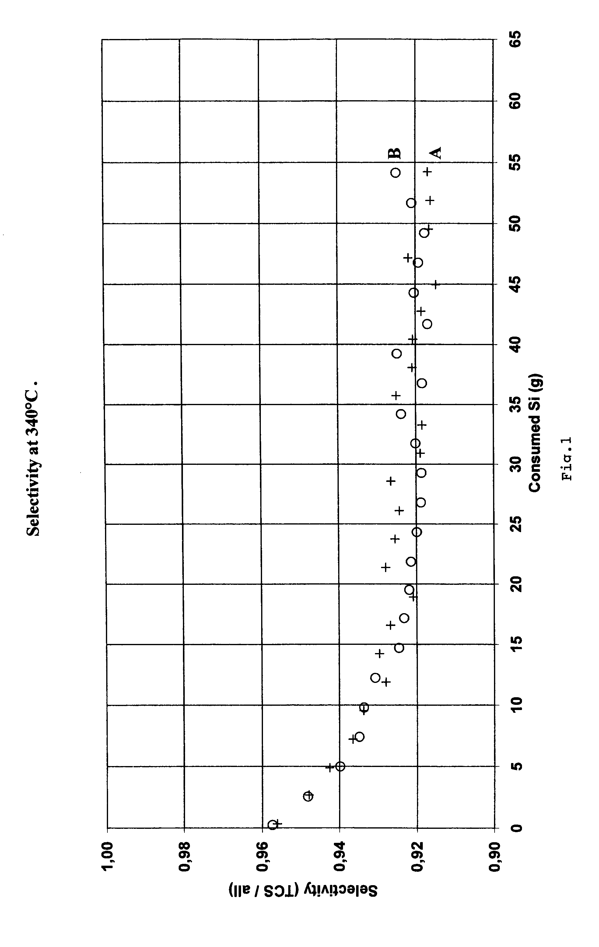
[0027]Metallurgical grade silicon produced by Elkem A S was crushed, milled and screened to a particle size between 180 and 250 μm, identified as sample A. Metallurgical silicon with similar composition to sample A was prepared. 46 ppm copper was alloyed into the refining ladle. The silicon was then cast, solidified and cooled to room temperature. The sample was then crushed and milled to a particle size between 180 and 250 μm. This sample has been identified as sample B.

[0028]The chemical analysis of silicon samples A and B are shown in Table 1.

TABLE 1SampleSampleSampleSampleSampleSampleABCDEFSi 99.4999.4999.4999.4999.4999.49wt %Al 0.140.160.140.140.160.16wt %Ca 0.0090.0030.0090.0090.0030.003wt %Fe 0.250.230.250.250.230.23wt %Zr ppmwSr ppmwPb ppmwBi ppmwAs ppmwZn ppmwCu 464646ppmwNi 475647475656ppmwMn 344034344040ppmwCr ppmwV 617961617979ppmwBa 80200724032ppmwTi 0,0140,0130,0140,0140,0130,013wt %Mo ppmwSb ppmwSn ppmwK ppmwP 151515151515ppmw

[0029]Samples A and B...

Example

Example 2

[0031]80 ppm by weight of barium in the form of barium silicide powder was mixed to silicon sample A in Table 1. This sample was denoted sample C, shown in Table 1.

[0032]200 ppm by weight of barium in the form of barium silicide powder was mixed to silicon sample A in Table 1. This sample was denoted sample D, shown in Table 1.

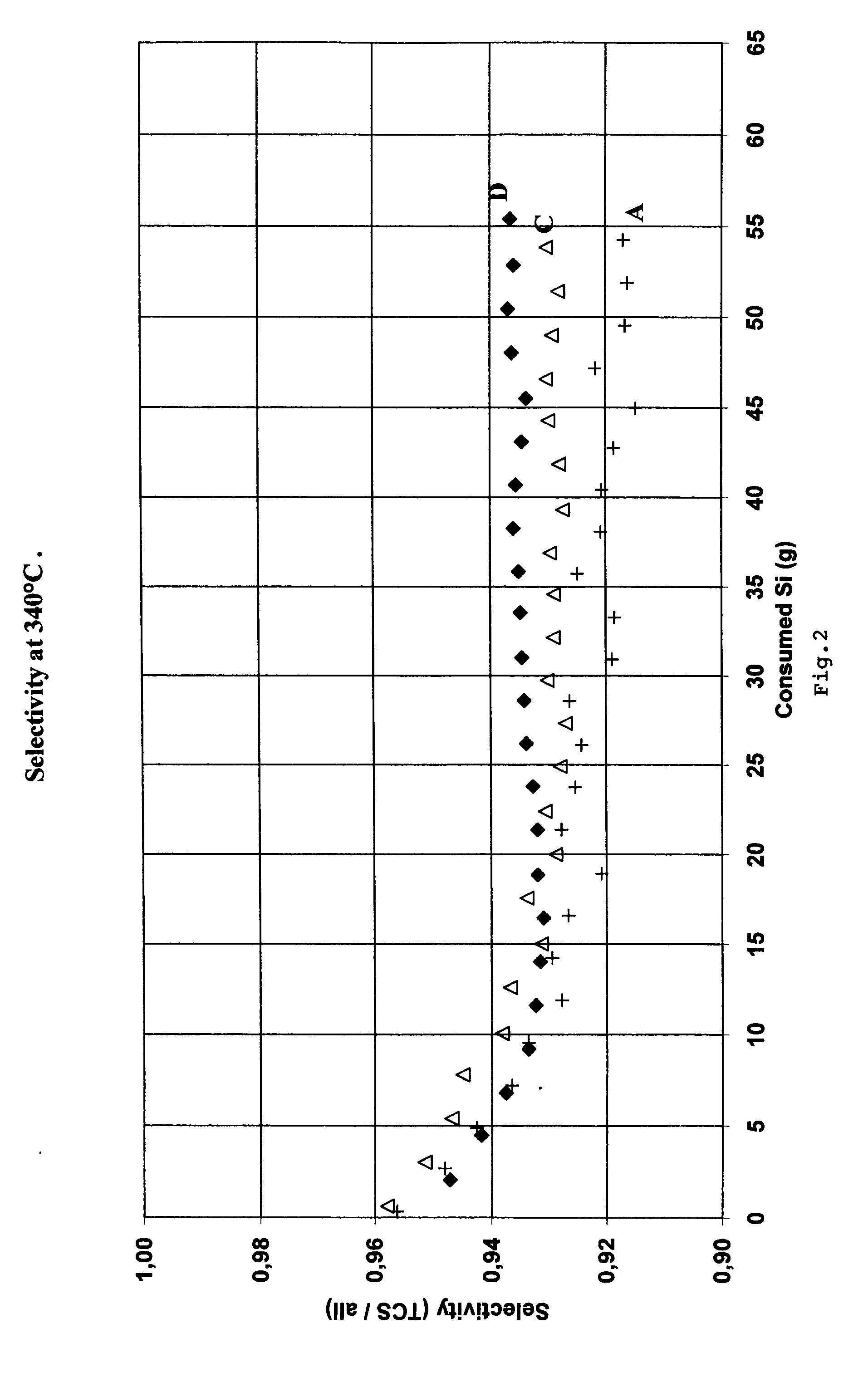
[0033]Samples A, C and D were used to produce trichlorosilane in the laboratory fluidized-bed reactor described above. The selectivity for TCS produced from samples A, C and D are shown in FIG. 2.

[0034]As can be seen from FIG. 2, the addition of 80 and 200 ppm by weight of barium as barium silicide to silicon resulted in an increase in selectivity. 100% of the HCl was converted in these runs.

Example

Example 3

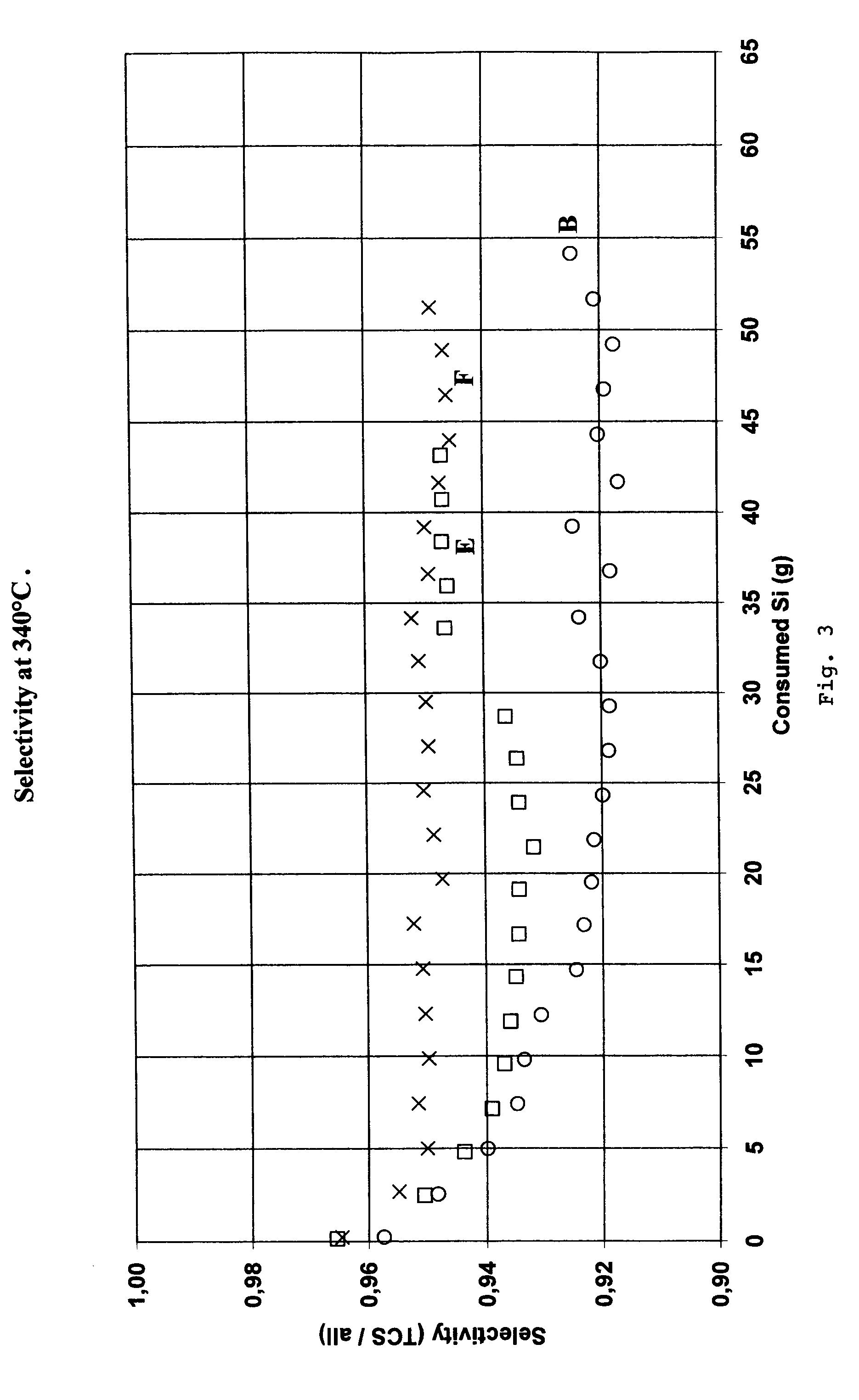
[0035]72 ppm by weight of barium added as barium oxide powder was mixed to the silicon sample B in Table 1. This sample containing both barium and copper was denoted sample E, shown in Table 1. A further sample F shown in Table 1 was made by adding 0.4 wt % of barium as barium oxide powder to 5 grams of sample B silicon. Silicon sample F was used as start material in the reactor. As silicon was consumed in the reactor, the barium-free silicon sample B was added to maintain 5 g silicon in the reactor. This gives an initial barium content of 0.4 wt % and no further addition of barium during the run. Barium added at the start-up of the experiment will partly remain in the reactor and thus the barium content in the reactor using sample F will essentially be constant during the test run. The chemical analysis of silicon samples B, E and F are shown in Table 1.

[0036]Sample B, E and F were used to produce trichlorosilane in the laboratory fluidized-bed reactor described above. The...


PUM


Abstract

The present invention relates to a method for the production of trichlorosilane by reaction of silicon with HCl gas at a temperature between 250° and 1100° C., and an absolute pressure of 0.5-30 atm in a fluidized bed reactor, in a stirred bed reactor or a solid bed reactor, where the silicon supplied to the reactor contains between 40 and 10.000 ppm by weight barium and optionally 40-10000 ppm by weight copper The invention further relates to silicon for use in the production of trichlorosilane by reaction of silicon with HCl gas, containing between 40 and 10.000 ppm by weight barium and optionally 40-10000 ppm by weight copper, the remaining except for normal impurities being silicon.

Description

FIELD OF INVENTION[0001]The present invention relates to a method for the production of trichlorosilane by reaction of silicon by HCl gas and silicon for the use in production of trichlorosilane.BACKGROUND ART [0002]In the method of production of trichlorosilane (TCS), metallurgical grade silicon is reacted with HCl gas in a fluidized bed reactor, in a stirred bed reactor or in a solid bed reactor. The process is generally carried out at a temperature between 250° and 1100° C. In the reaction other volatile silanes than TCS are formed, mainly silicon tetrachloride (STC). Since TCS normally is the preferred product, the selectivity of the reaction given as the molar ratio of TCS / (TCS+other silanes) is an important factor. The other important factor is the reactivity of the silicon, measured as first pass HCl conversion. Preferably more than 90% of HCl is converted to silanes, but industrially lower reactivity can be observed.[0003]The selectivity and reactivity will depend strongly o...

Claims


Application Information

Patent Timeline
IPC IPC(8): C01B33/107
CPCC01B33/10763
Inventor HOEL, JAN-OTTOKJENLI, HENNINGRONG, HARRY MORTENROE, TORBJORNBJORDAL, JOSTEIN
Owner ELKEM
Why Eureka
Try Eureka