
Trench forming method, metal wiring forming method, and method of manufacturing thin film transistor array panel

Active Publication Date: 2013-09-26
SAMSUNG DISPLAY CO LTD
View PDF5 Cites 7 Cited by
  • Summary
  • Abstract
  • Description
  • Claims
  • Application Information

AI Technical Summary

Benefits of technology

The invention provides methods for forming trenches and metal wirings with improved selectivity and reduced generation of metallic foreign substances. By using amorphous carbon layers as a mask, instead of metal masks, the etching process is more selective and contamination of the trench is avoided. This results in better trench formation and reduced residual films after the etching process.

Problems solved by technology

When a photo etching process using an existing photosensitive film as a mask is used to form a trench, selectivity of etching is disadvantageously very low.
A method of performing etching by using a metal mask instead of a photosensitive film is being studied, but if a metal mask is used, residue is produced in a trench so that a bottom of the trench cannot be etched, causing residual films to be left.

Method used


Image

  • Trench forming method, metal wiring forming method, and method of manufacturing thin film transistor array panel
  • Trench forming method, metal wiring forming method, and method of manufacturing thin film transistor array panel
  • Trench forming method, metal wiring forming method, and method of manufacturing thin film transistor array panel

Examples


Embodiment Construction

[0039]The invention will be described more fully hereinafter with reference to the accompanying drawings, in which exemplary embodiments of the invention are shown. As those skilled in the art would realize, the described embodiments may be modified in various different ways, all without departing from the spirit or scope of the invention.

[0040]In the drawings, the thickness of layers, films, panels, regions, etc., are exaggerated for clarity. Like reference numerals designate like elements throughout the specification. As used herein, connected may refer to elements being physically and / or electrically connected to each other. As used herein, the term “and / or” includes any and all combinations of one or more of the associated listed items.

[0041]It will be understood that when an element such as a layer, film, region, or substrate is referred to as being “on” another element, it can be directly on the other element or intervening elements may also be present. In contrast, when an el...


PUM


Abstract

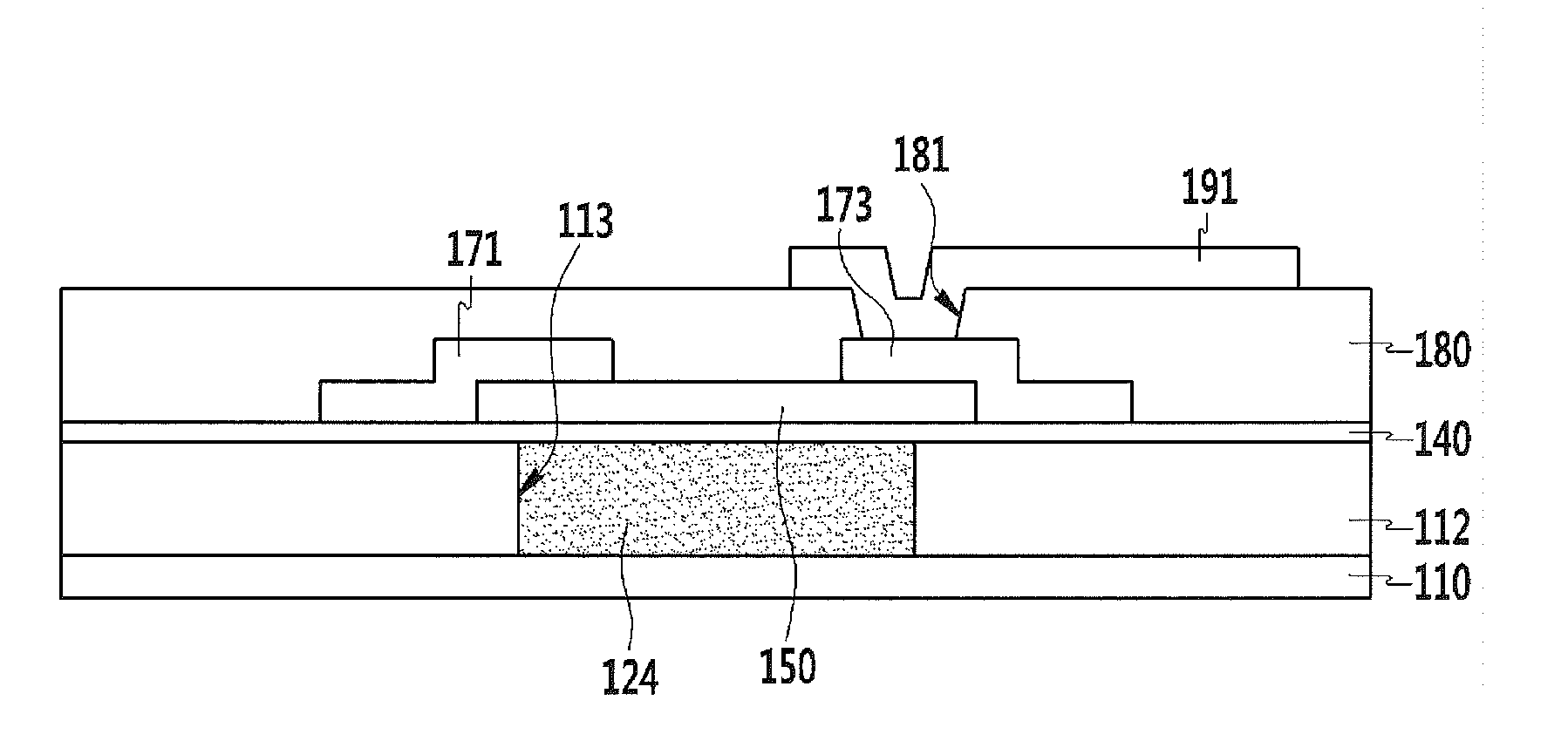
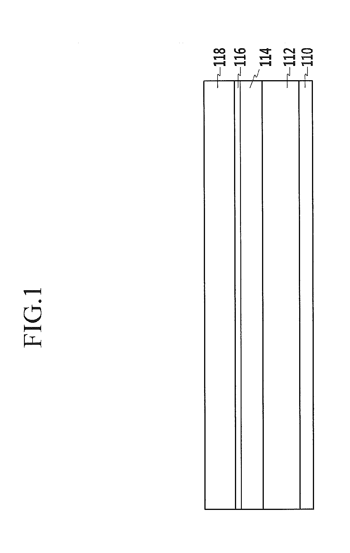
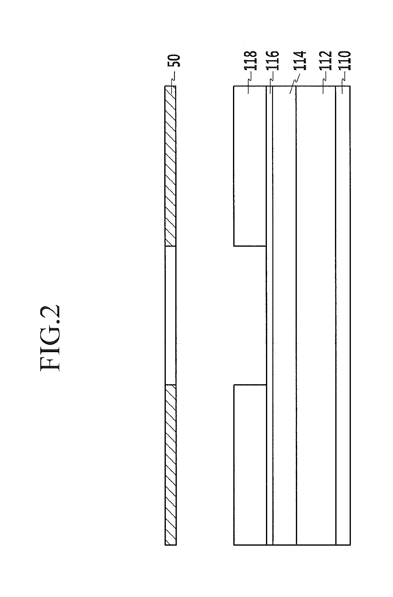
A method of forming a thin film transistor array panel includes: forming a first insulating layer on a substrate; forming an amorphous carbon layer on the first insulating layer; forming a second insulating layer on the amorphous carbon layer; forming an opening in the amorphous carbon layer by patterning the second insulating layer and the amorphous carbon layer; and forming a trench in the first insulating layer by etching the first insulating layer, the etching the first insulating layer using the amorphous carbon layer including the opening as a mask.

Description

[0001]This application claims priority to Korean Patent Application No. 10-2012-0029553 filed on Mar. 22, 2012, and all the benefits accruing therefrom under 35 U.S.C. §119, the entire contents of which are incorporated herein by reference.BACKGROUND[0002]1. (a) Field[0003]The invention relates to a trench forming method, a metal wiring forming method, and a method of manufacturing a thin film transistor array panel. More particularly, the invention relates to a trench forming method which allows etching at a high selectivity and prevents an interior of a trench from being contaminated, a metal wiring forming method, and a method of manufacturing a thin film transistor array panel.[0004]2. (b) Description of the Related Art[0005]In general, a thin film transistor (“TFT”) is used as a switching device for independently driving each pixel in a flat panel display device such as a liquid crystal display or an organic light emitting diode display. A thin film transistor array panel of th...

Claims


Application Information

Patent Timeline
IPC IPC(8): H01L21/336H01L21/28H01L21/311
CPCH01L21/28H01L21/31144H01L27/1262H01L27/124H01L27/1248H01L21/76802H01L21/3081H01L21/3085H01L21/3086H01L21/31116H01L21/3212H01L27/1288
Inventor RYU, YONG-HWANKIM, DAE HOPARK, HONG SICKCHOI, SHIN IL
Owner SAMSUNG DISPLAY CO LTD
Learn More