Eureka AIR delivers breakthrough ideas for toughest innovation challenges, trusted by R&D personnel around the world.

Flexible and Scalable Modular Control System for Transport Refrigeration Units

a modular control system and refrigeration unit technology, applied in electric controllers, program control, instruments, etc., can solve the problems of limited flexibility and scalability of existing transport refrigeration controls, difficult or impossible addition of additional features and functionality, and limited need for storage or monitoring capabilities

Inactive Publication Date: 2013-06-06
CARRIER CORP
View PDF4 Cites 6 Cited by
  • Summary
  • Abstract
  • Description
  • Claims
  • Application Information

AI Technical Summary

Benefits of technology

The patent text describes a control system for a refrigeration unit that is flexible and scalable. The system includes a user interface, power control module, and two modules with flexible input / output connectors. The system can be easily configured and identifies any improper operations through an internal data recorder, which can be reported through the user interface. The technical effects of the patent include efficient, flexible, and scalable control for refrigeration systems.

Problems solved by technology

Existing transport refrigeration controls are of an integrated design and have limited flexibility and scalability.
Adding additional features and functionality is often difficult or impossible.
For instance, the need for more storage or monitoring capabilities is limited to the amount of memory and components originally designed into the control system.
The limited storage and monitoring capacities limits diagnostic and prognostic capabilities.
When used on a simpler system, the unused inputs and outputs on the complex system become wasted.
Alternatively, the simple system with fixed inputs and outputs can not be upgraded with additional inputs and outputs to meet the needs of the complex system.
Thus, existing integrated controls for transport refrigeration units lack flexibility and scalability.

Method used


Image

  • Flexible and Scalable Modular Control System for Transport Refrigeration Units
  • Flexible and Scalable Modular Control System for Transport Refrigeration Units
  • Flexible and Scalable Modular Control System for Transport Refrigeration Units

Examples


Embodiment Construction

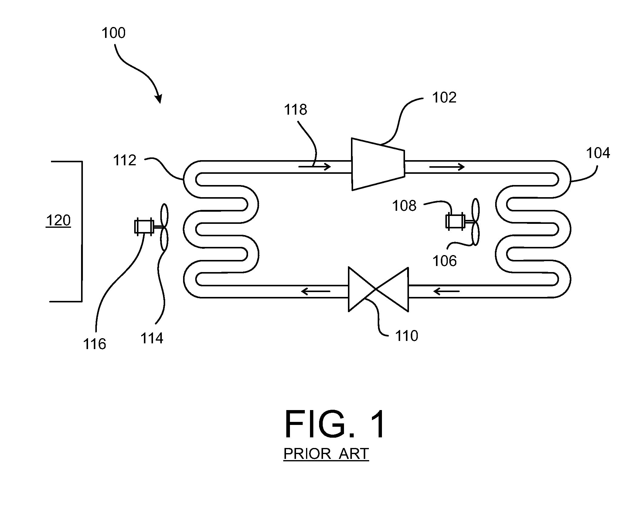
[0017]FIG. 1 illustrates a block diagram of a basic refrigeration system 100. The refrigeration system 100 includes a compressor 102, a condenser coil 104, a condenser fan 106 with a condenser motor 108, an expansion valve 110, an evaporator coil 112, an evaporator fan 114 with an evaporator motor 116, and refrigerant 118. The refrigerant 118 is a fluid used to absorb and transfer heat. Examples include, but are not limited to, fluorinated carbons, chlorinated carbons and brominated carbons. The refrigerant 118 absorbs heat by evaporating from a liquid to a gas at a low temperature and pressure, and releases heat by condensing from gas back to liquid at a higher temperature and pressure.

[0018]In the depicted example, the refrigerant 118 enters the compressor 102 in a low-temperature, low-pressure gas state. The compressor 102 compresses the refrigerant 118 to a high-temperature, high-pressure gas state. The refrigerant 118 then flows through the condenser coil 104, wherein the refri...


PUM


Abstract

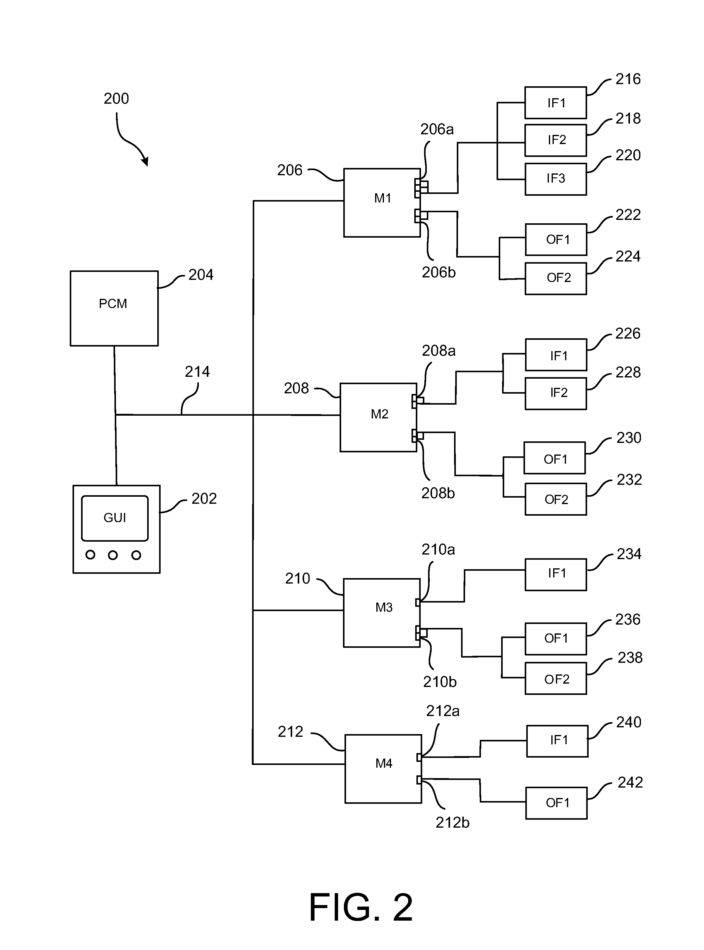
A control system for a refrigeration unit is disclosed. The control system may include a user interface, an interface bus, a power control module, a first module, and a second module. The interface bus may communicatively couple the user interface, the power control module, the first module, and the second module. The user interface may be capable of receiving and dispatching information. The power control module may be capable of distributing and monitoring power to the control system. The second module may have at least one connector with flexible input and output configuration capabilities. The first module may have a controller and at least one connector with flexible input and output configuration capabilities.

Description

CROSS-REFERENCE TO RELATED APPLICATION[0001]This is an international patent application filed pursuant to the Patent Cooperation Treaty claiming priority under 35 USC §119(e) to U.S. Provisional Patent Application Ser. No. 61 / 373,504 filed on Aug. 13, 2010.FIELD OF THE DISCLOSURE[0002]The present disclosure generally relates to a transport refrigeration unit and, in particular, relates to a flexible and scalable modular control system for a transport refrigeration unit with diagnostic and prognostic capabilities.BACKGROUND OF THE DISCLOSURE[0003]Refrigeration systems are commonly used for cooling a desired area. Refrigeration works by removing heat from an enclosed area and transferring that heat to an external atmosphere located outside of the enclosed area. Refrigeration systems are widely used in residential and commercial food refrigerators, air-conditioning units in homes and automobiles, and cargo areas of ships and trucks.[0004]Mobile refrigeration systems used to condition f...

Claims


Application Information

Patent Timeline
IPC IPC(8): G05B11/01
CPCG05B11/01G05B19/0421
Inventor DUDLEY, KEVINSTODDARD, PAULWASER, DANIEL L.DESMARAIS, BRETT A.CHAMPAGNE, DEBORAH A.HANNON, JOHN F.
Owner CARRIER CORP
Why Eureka
Eureka Blog
Learn More