
Air conditioner

a technology for air conditioners and compressors, applied in mechanical equipment, refrigeration components, light and heating equipment, etc., can solve the problems of excessive evaporation or condensation capability of outdoor heat-exchangers, excessive discharge pressure of compressors, and difficult operation, so as to maintain the reliability of compressors and high pressure loss

Inactive Publication Date: 2013-06-13
SAMSUNG ELECTRONICS CO LTD
View PDF4 Cites 45 Cited by
  • Summary
  • Abstract
  • Description
  • Claims
  • Application Information

AI Technical Summary

Benefits of technology

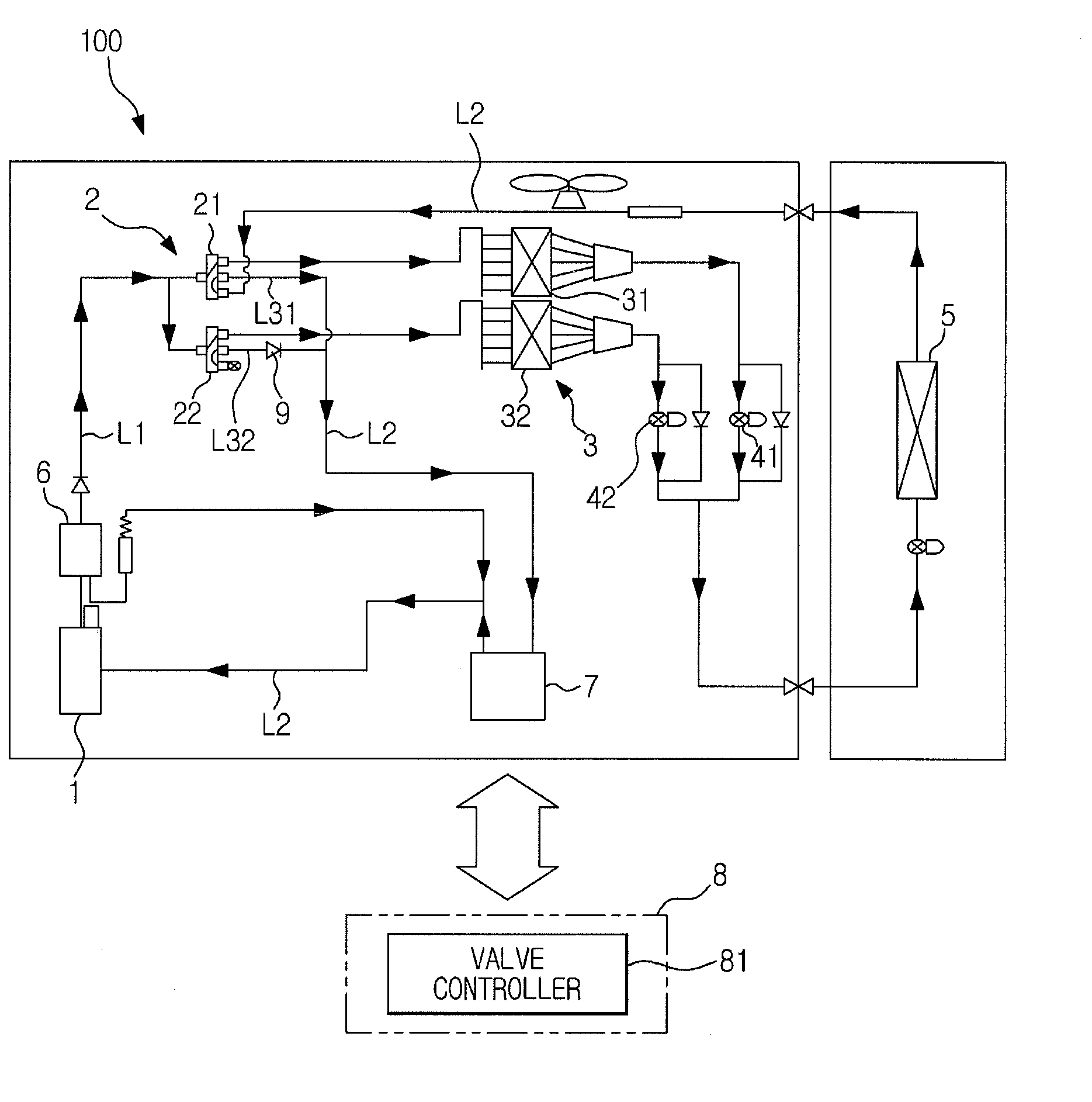
This patent is about an air conditioner that can control the capacity of its outdoor heat-exchanger without using high-pressure valves that have high pressure loss. This prevents the accumulation of refrigerant in the outdoor heat-exchanger when it is stopped, which ensures the reliability of the compressor and maintains the heating or cooling efficiency. The air conditioner uses two 4-way valves instead of one large electronic valve, which reduces costs. The air conditioner also includes a pressure meter and a valve controller to measure and control the compressor's discharge pressure and the expansion valves of the outdoor heat-exchanger. This valve controller ensures the proper operation and prevents damage to the air conditioner under various operating conditions. Overall, this patent provides a technical solution to control the capacity of the outdoor heat-exchanger in an efficient and cost-effective manner.

Problems solved by technology

For example, when an air conditioner is operated under low-load operating conditions, i.e. during heating operation under low indoor air-conditioning load and high outside temperature conditions or cooling operation under low indoor air-conditioning load and low outside temperature, evaporation or condensation capability of an outdoor heat-exchanger excessively increases, causing problematic operation.
More specifically, if evaporation capability of the outdoor heat-exchanger excessively increases during heating operation under low-load operating conditions, discharge pressure of a compressor also excessively increases to exceed an upper limit thereof, which causes sudden shutdown of the compressor by a protective circuit.
On the other hand, if condensation capability of the outdoor heat-exchanger excessively increases during cooling operation under low-load operating conditions, discharge pressure of the compressor decreases and has only a slight difference from suction pressure of the compressor, which causes an inappropriate compression ratio and makes it difficult to maintain reliability of the compressor.
However, the conventional air conditioner constructed as described above may suffer from high pressure loss during flow of refrigerant due to the plurality of electronic on-off valves provided at front and rear sides of the respective outdoor heat-exchangers, thus deteriorating heating or cooling performance.
However, using a large-scale electronic on-off valve to reduce pressure loss may not be beneficial in terms of cost.
In addition, although it may be contemplated to reduce the number of electronic on-off valves, for example, by installing the electronic on-off valve only at the front or rear side of each outdoor heat-exchanger, this may cause accumulation of refrigerant in the outdoor heat-exchanger when the outdoor heat- exchanger is stopped, thus deteriorating the flow rate of refrigerant and cooling or heating performance.
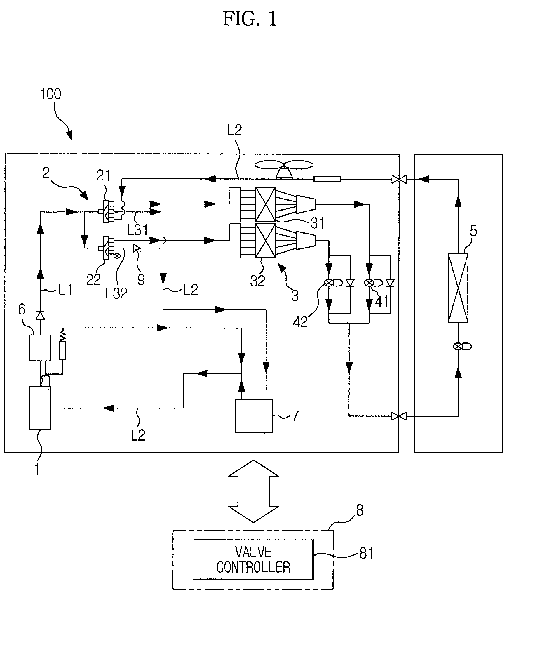
With the above-described configuration, under low-load operating conditions, the second expansion valve is closed and the second 4-way valve is switched to connect the gas line of the second outdoor heat-exchanger to the suction port of the compressor so as to prevent refrigerant from flowing to the second outdoor heat-exchanger, which results in reduction in the capacity of the outdoor heat-exchanger unit.

Method used


Image

  • Air conditioner
  • Air conditioner
  • Air conditioner

Examples


first embodiment

Configuration of First Embodiment

[0035]The first-described embodiment of the present disclosure will now be described with reference to the drawings.

[0036]Referring to FIG. 1, an air conditioner, designated by reference numeral 100, according to the first-described embodiment includes a refrigerant circuit constructed by annular connection of a compressor 1, a 4-way valve unit 2, an outdoor heat-exchanger unit 3, and an indoor heat-exchanger unit 5. In the air conditioner 100, the 4-way valve unit 2 is used to connect a connection for a discharge port or a suction port of the compressor 1 to any one of the outdoor heat-exchanger unit 3 or the indoor heat-exchanger unit 5, such that each heat-exchanger unit functions as a condenser or an evaporator to enable selective switching of room cooling and room heating. In the air conditioner 100 according to the first-described embodiment, to change heat-exchange capabilities of the outdoor heat-exchanger unit 3 based on outside temperature ...

second embodiment

Configuration of Second Embodiment

[0056]The air conditioner 100 according to the secondly-described embodiment of the present disclosure will now be described. Elements corresponding to those of the air conditioner 100 of the first-described embodiment will be designated by the same reference numerals.

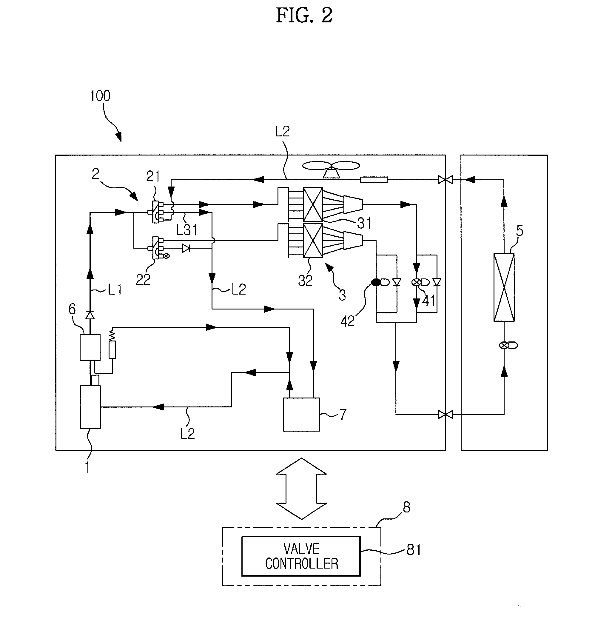
[0057]The air conditioner 100 of the secondly-described embodiment includes not only a configuration for variable capacity of the outdoor heat-exchanger unit 3 via switching of flow of refrigerant to any one of a plurality of outdoor heat-exchangers, but also a configuration for defrosting of each outdoor heat-exchanger.

[0058]More specifically, the air conditioner 100 of the secondly-described embodiment, as illustrated in FIG. 7, differs from the air conditioner 100 of the first-described embodiment with respect to a configuration of the 4-way valve unit 2. Additionally, the air conditioner 100 of the secondly-described embodiment further includes an auxiliary heat-exchanger 33 provid...


PUM


Abstract

An air conditioner which controls capacity of an outdoor heat-exchanger unit without an on-off valve that exhibits high pressure loss, which prevents accumulation of refrigerant in an outdoor heat-exchanger, and which maintains reliability of a compressor or refrigeration cycle. The air conditioner includes a first expansion valve on a liquid line of a first outdoor heat- exchanger, a second expansion valve on a liquid line of a second outdoor heat-exchanger, a first connection line to connect a suction line to one port of the first 4-way valve, the suction line connecting a suction port of the compressor and an indoor heat-exchanger unit, a second connection line to connect the suction line to one port of the second 4-way valve, and a check valve provided on the second connection line to allow flow of refrigerant only from the second 4-way valve to the suction line.

Description

CROSS-REFERENCE TO RELATED APPLICATIONS[0001]This application claims the benefit of Korean Patent Application No. 10-2012-0114473, filed on Oct. 15, 2012 in the Korean Intellectual Property Office and of Japanese Patent Application No. 2011-271481, filed on Dec. 12, 2011 in the Japanese Intellectual Property Office, the disclosures of which are incorporated herein by reference.BACKGROUND[0002]1. Field[0003]Embodiments of the present disclosure relate to an air conditioner which includes an outdoor heat-exchanger unit constructed by connecting a plurality of outdoor heat-exchangers in a row, capacity of the outdoor heat-exchanger unit being controllable during low-load operation.[0004]2. Description of the Related Art[0005]For example, when an air conditioner is operated under low-load operating conditions, i.e. during heating operation under low indoor air-conditioning load and high outside temperature conditions or cooling operation under low indoor air-conditioning load and low ou...

Claims


Application Information

Patent Timeline
Patent Type & Authority Applications(United States)
IPC IPC(8): F25B49/02F25B13/00
CPCF25B49/02F25B2700/1933F25B41/04F25B41/046F25B47/025F25B2313/005F25B2313/006F25B2313/0211F25B2313/025F25B2313/0251F25B2313/02522F25B2313/0253F25B2313/02742F25B2313/02743F25B2313/0292F25B2313/0315F25B2400/13F25B2700/1931F25B13/00F25B41/20F25B41/24
Inventor NOBUHIRO, NAKAGAWA
Owner SAMSUNG ELECTRONICS CO LTD
Learn More