Electromagnetic Wave Transmission Medium and Electromagnetic Wave Transmission System

a transmission system and electromagnetic wave technology, applied in the direction of transmission system of fixed station waveguides, near-field systems using receivers, line-transmission details, etc., can solve problems such as loss of transmission or expansion of interference waves, and achieve the effect of reducing electromagnetic leakag

Inactive Publication Date: 2013-06-13
HITACHI LTD
View PDF4 Cites 11 Cited by
  • Summary
  • Abstract
  • Description
  • Claims
  • Application Information

AI Technical Summary

Benefits of technology

[0008]According to the present invention, there is realized a reduction in an electromagnetic leakage when an electromagnetic wave having a large power is transmitted by properly using two of the mesh conductors.

Problems solved by technology

However, since according to the above-described system, the electromagnetic wave effused from the mesh conductor is used, in a case where an electromagnetic wave leaked from the mesh conductor is considerable, there poses a technical problem that a transmission loss or an interference wave is enlarged.

Method used


Image

  • Electromagnetic Wave Transmission Medium and Electromagnetic Wave Transmission System
  • Electromagnetic Wave Transmission Medium and Electromagnetic Wave Transmission System
  • Electromagnetic Wave Transmission Medium and Electromagnetic Wave Transmission System

Examples


first embodiment

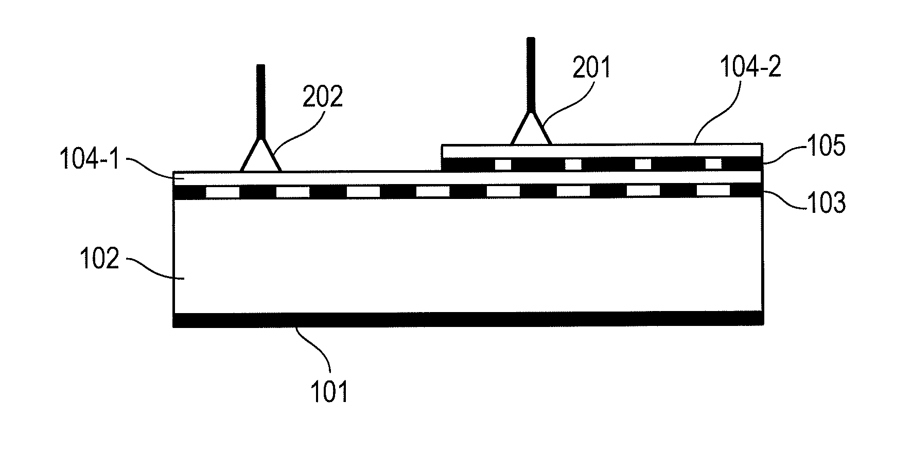
[0017]First, an explanation will be given of a first embodiment in reference to the drawings. In the following, a case of transmitting an electromagnetic wave having a relatively large power is described as “power feeding”, and a case of transmitting an electromagnetic wave having a relatively small power is described as “transmission” for convenience of explanation. However, an electromagnetic wave transmission medium according to the present invention is not necessarily on the premise of being used limitedly to a combination of “power feeding” and “communication”. That is, the present invention can be used for an arbitrary transmission use so far as two kinds of electromagnetic waves having different powers are transmitted.

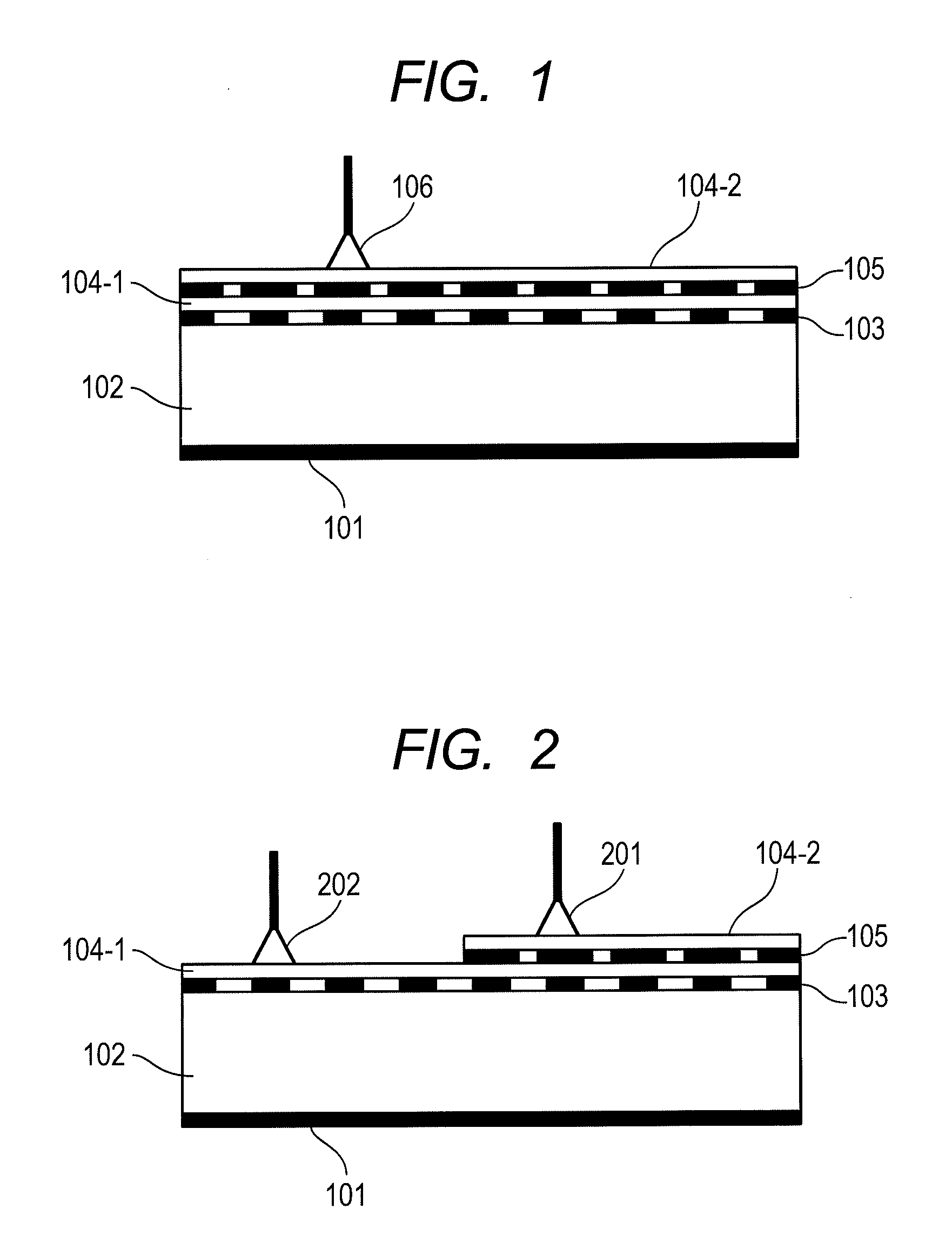
[0018]FIG. 1 shows an example of a sectional structure of an electromagnetic wave transmission medium according to the first embodiment. In the drawing, notation 101 designates a conductor layer, notation 102 designates a dielectric layer, notation 103 designate...

second embodiment

[0029]According to the first embodiment, there is shown a case in which the ratio of conductive area of the mesh conductor layer 105 on the upper layer is higher than the ratio of conductive area of the mesh conductor layer 103 on the lower layer side.

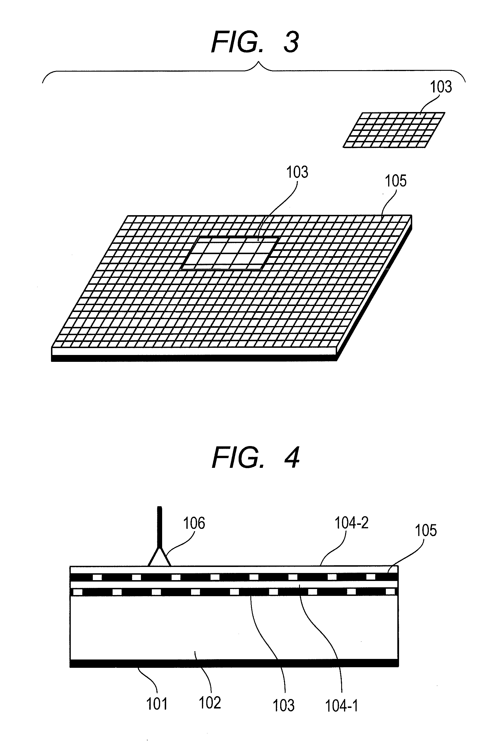
[0030]However, in a case of adopting a laminated structure of two mesh conductors, there can also be adopted a structure in which the ratio of conductive area of the mesh conductor layer 105 on the upper layer side (electromagnetic wave interface side) is equal to the ratio of conductive area of the mesh conductor layer 103 on the lower layer side (dielectric layer side), or lower than the ratio of conductive area of the mesh conductor layer 103.

[0031]FIG. 4 shows an example of a sectional structure of an electromagnetic wave transmission medium in a case in which the conduction densities of the mesh conductor layers 103 and 105 are the same. Incidentally, FIG. 4 is shown by attaching the same notation to a portion of FIG. 4 in corresp...

third embodiment

[0033]An explanation has been given of a structure of laminating two of the mesh conductor layers according to the above-described two embodiments. However, in a case in which a position of a region used for power feeding is determined beforehand, there can also be adopted a structure of arranging two mesh conductor layers having different conduction densities on the same flat face as in the present embodiment. Also in the case of the embodiment, assume that two mesh conductor layers signify those for power feeding and for communication, and a ratio of conductive area of a mesh conductor layer for power feeding is lower than a ratio of conductive area of a mesh conductor layer for communication.

[0034]FIG. 5 shows an example of a sectional structure of an electromagnetic wave transmission medium of this kind. An electromagnetic transmission medium shown in FIG. 5 is configured by two kinds of mesh conductor layers having different densities. In the drawing, notation 501 designates a ...


PUM


Abstract

The disclosed electromagnetic wave transmission medium prevents electromagnetic leakage during high-power electromagnetic wave transmission. The sheet-form electromagnetic wave transmission medium is configured from a first mesh conductor used in transmission of electromagnetic waves having a first power; and a second mesh conductor used in transmission of electromagnetic waves having a second power. By using two mesh conductors, when said sheet-form electromagnetic wave transmission medium is used, the conduction density of the surface region where electromagnetic waves are extracted to be used for power supply assumes a coarser state than that of the other surface region.

Description

TECHNICAL FIELD[0001]The present invention relates to an electromagnetic transmission medium in a face-form (sheet-form) which can simultaneously transmit plural kinds of electromagnetic waves while facilitating a reduction in an electromagnetic leakage as well as a transmission system using the medium for a transmission line.BACKGROUND ART[0002]There is proposed a combination of an electromagnetic transmission medium interposing a dielectric by one mesh conductor and one sheet-form conductor, and an electromagnetic wave interface of extracting an electromagnetic wave effused from the mesh conductor as a transmission system realizing noncontact electromagnetic wave transmission by a simple configuration.[0003]According to the system described above, the electromagnetic wave effused from the mesh conductor can be extracted from an arbitrary position of the sheet-form conductor. Therefore, attention is paid to the above-described system as one of means of realizing communication or po...

Claims


Application Information

Patent Timeline
Patent Type & Authority Applications(United States)
IPC IPC(8): H04B3/52H04B5/02H04B13/00
CPCH04B3/52H01Q13/20H01Q1/007H04B3/50
Inventor YAMAMOTO, KEISUKESHINODA, HIROSHITERADA, TAKAHIDE
Owner HITACHI LTD
Why Eureka
Try Eureka