
Optical Star Coupler for Plastic Optical Fibers

a technology of optical star coupler and plastic optical fiber, which is applied in the direction of optical elements, instruments, manufacturing tools, etc., can solve the problems of glass optical fiber devices providing poor performance when used with plastic optical fibers, optical fiber types may be more expensive than desired, etc., and achieve the effect of reducing the size of the channel

Active Publication Date: 2013-06-13
THE BOEING CO
View PDF7 Cites 21 Cited by
  • Summary
  • Abstract
  • Description
  • Claims
  • Application Information

AI Technical Summary

Benefits of technology

The patent allows for various ways to achieve the same features and functions. These features and functions can be used independently or combined in different ways to achieve further details.

Problems solved by technology

These types of optical fibers may more expensive than desired as compared to the wires that they replace.
However, differences in material and physical characteristics between glass optical fibers and plastic optical fibers may result in devices designed for glass optical fibers providing poor performance when used with plastic optical fibers.

Method used


Image

  • Optical Star Coupler for Plastic Optical Fibers
  • Optical Star Coupler for Plastic Optical Fibers
  • Optical Star Coupler for Plastic Optical Fibers

Examples


Embodiment Construction

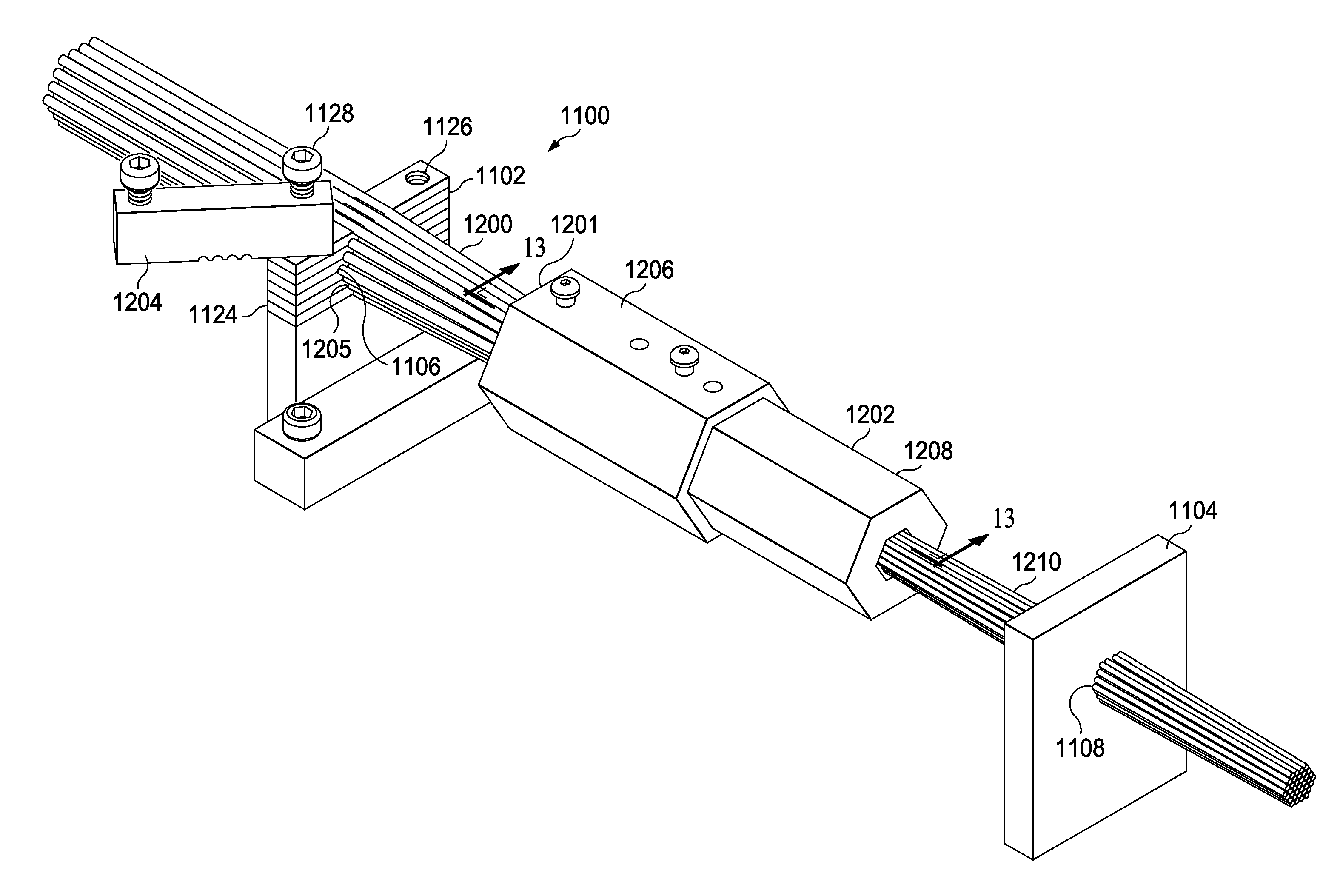
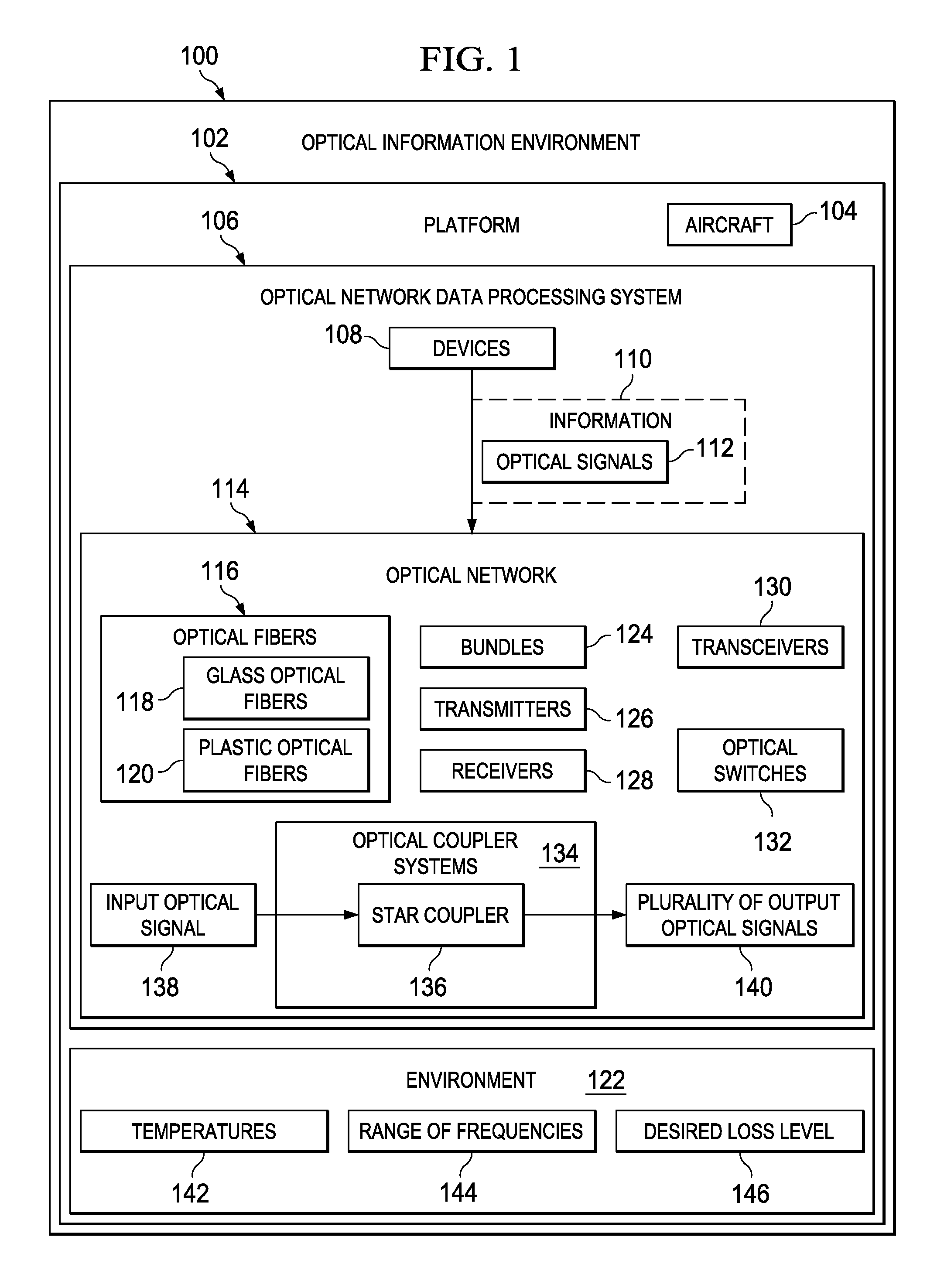
[0033]The different illustrative embodiments recognize and take into account one or more different considerations. For example, the different illustrative embodiments recognize and take into account that the use of optical networks in a vehicle, such as an aircraft, requires an ability of the components to withstand the operating environment of the aircraft. For example, in an aircraft, optical fibers should be able to withstand temperature ranges that may be encountered in the aircraft. These temperature ranges may be from about −40 degrees Celsius to about 105 degrees Celsius. The different illustrative embodiments also recognize and take into account that the optical fibers used should provide an ability to carry optical signals in a range of frequencies used by transmitters, receivers, transceivers, or other similar devices. Additionally, the different illustrative embodiments also recognize and take into account that with the use of optical fibers, reduced loss in the transmiss...


PUM

PropertyMeasurementUnit
temperatureaaaaaaaaaa
widthaaaaaaaaaa
widthaaaaaaaaaa

Abstract

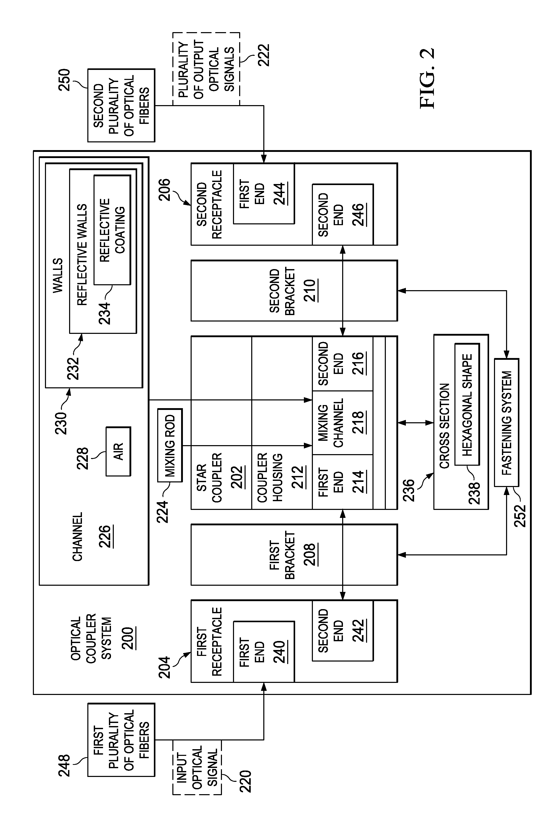
A method and apparatus for assembling an optical coupler system. A first plurality of optical fibers is connected to a first receptacle using an alignment system to align the first plurality of optical fibers in the first receptacle. A second plurality of optical fibers is connected to a second receptacle using the alignment system to align the second plurality of optical fibers in the second receptacle. The first receptacle is connected to a star coupler. The first plurality of optical fibers is optically connected to a mixing channel in the star coupler. The second receptacle is connected to the star coupler. The second plurality of optical fibers is optically connected to the mixing channel in the star coupler.

Description

BACKGROUND INFORMATION[0001]1. Field[0002]The present disclosure relates generally to transmitting optical signals and, in particular, to optical devices. Still more particularly, the present disclosure relates to a method and apparatus for sending signals using an optical star coupler.[0003]2. Background[0004]In sending information between devices, optical signals may be used to send the information. The information is encoded in the optical signals sent from one device to another device. With this type of medium, a transmitter encodes a message in an optical signal. The optical signal is sent through a medium, such as an optical fiber, to a receiver. The receiver then decodes the message from the received optical signal. With this type of transmission, networks using wires may be replaced or supplemented to include optical fibers over which optical signals are sent.[0005]An optical fiber is a flexible, transparent fiber that may be made of silica, plastic, or other materials havin...

Claims


Application Information

Patent Timeline
Patent Type & Authority Applications(United States)
IPC IPC(8): G02B6/26B23P11/00G02B6/42
CPCG02B6/368Y10T29/49826G02B6/2808G02B6/3672
Inventor KOSHINZ, DENNIS GARYCHAN, ERIC Y.
Owner THE BOEING CO
Learn More