
Interbody Cage for Spine Fusion

a technology of interbody cage and spine, which is applied in the field of interbody cage, can solve the problems of high difficulty in making and manufacturing cost of this conventional interbody cage, and the filler inside the interbody cage may easily flow away, so as to achieve the effect of lowering the difficulty and cost of manufacturing

Inactive Publication Date: 2013-06-13
METAL INDS RES & DEV CENT
View PDF41 Cites 7 Cited by
  • Summary
  • Abstract
  • Description
  • Claims
  • Application Information

AI Technical Summary

Benefits of technology

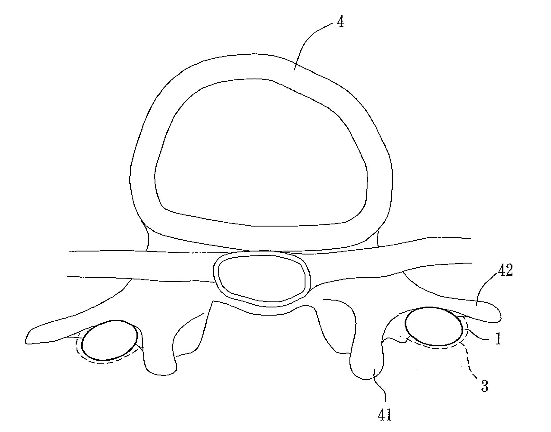
The invention is an interbody cage that has a simple and integrated structure, without any joint between separate members, to reduce manufacturing difficulty and cost. The cage prevents soft tissues from entering and securely holds the filler to prevent it from flowing away. It can be used in any position of a patient with spinal disease to promote bone growth.

Problems solved by technology

However, the filler inside the interbody cage may easily flow away due to intrusion of soft tissues, which usually grow faster than bone tissues, in the interbody cage or circulatory system if the meshes of the interbody cage are not well designed, and thus this implant made of the interbody cage and filler will not achieve a desirable performance.
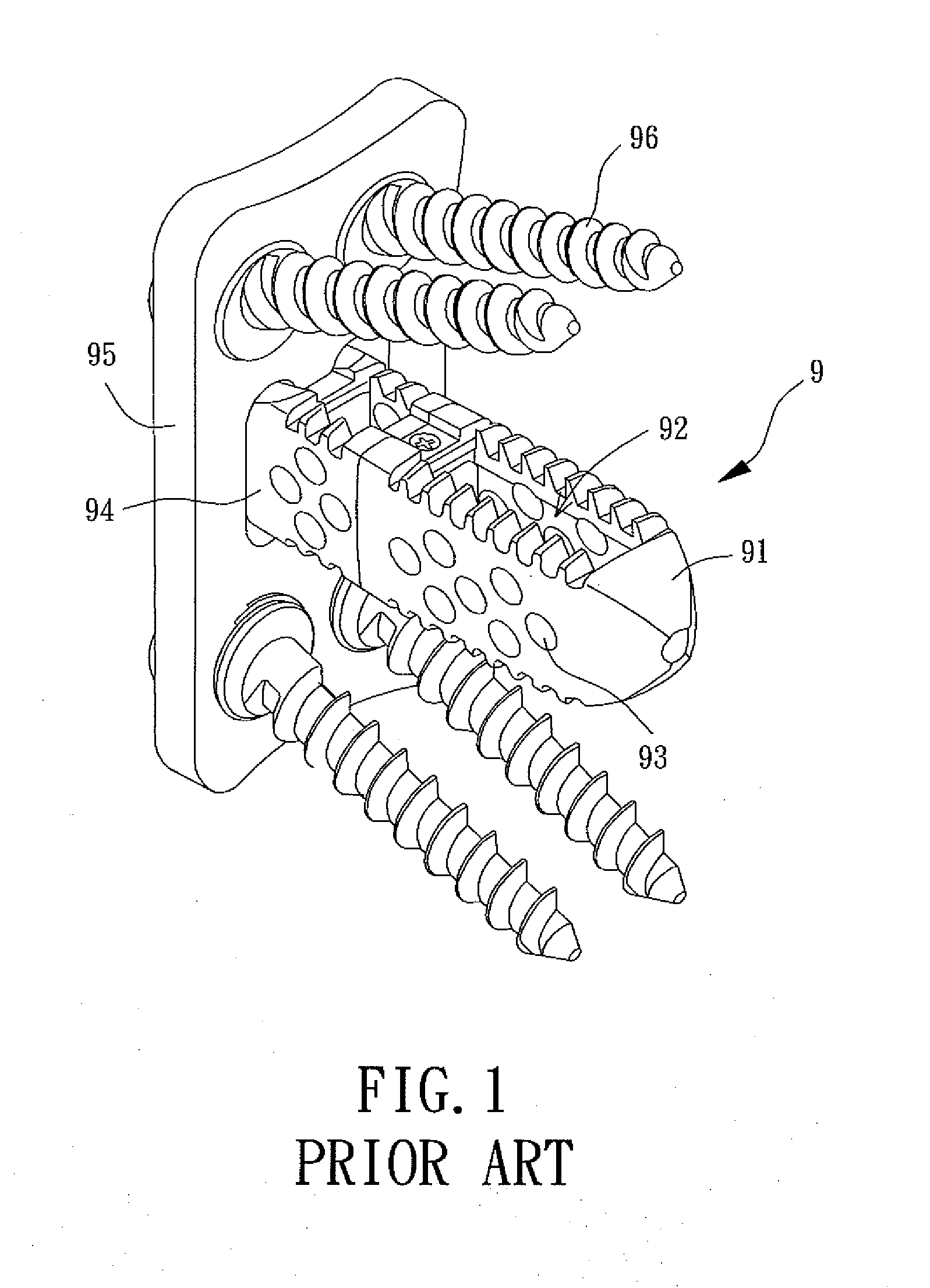
Moreover, the complexity, difficulty in made and manufacture cost of this conventional interbody cage 9 are high since the interbody cage 9 can only be shaped by 3D laser carving and spark-discharge forming.
Furthermore, the filler loss problem due to soft tissues' intrusion and circulatory system may easily occur in this interbody cage 9 since the room 92 and holes 93 are not particularly designed to block the intruded soft tissues and the filler inside the room 92.
Accordingly, the conventional interbody cage 9 cannot effectively enhance the growing speed of a defective bone but only serves as a support, and thus the interbody cage 9 cannot help a lot in recovery of the bone.

Method used


Image

  • Interbody Cage for Spine Fusion
  • Interbody Cage for Spine Fusion
  • Interbody Cage for Spine Fusion

Examples


Embodiment Construction

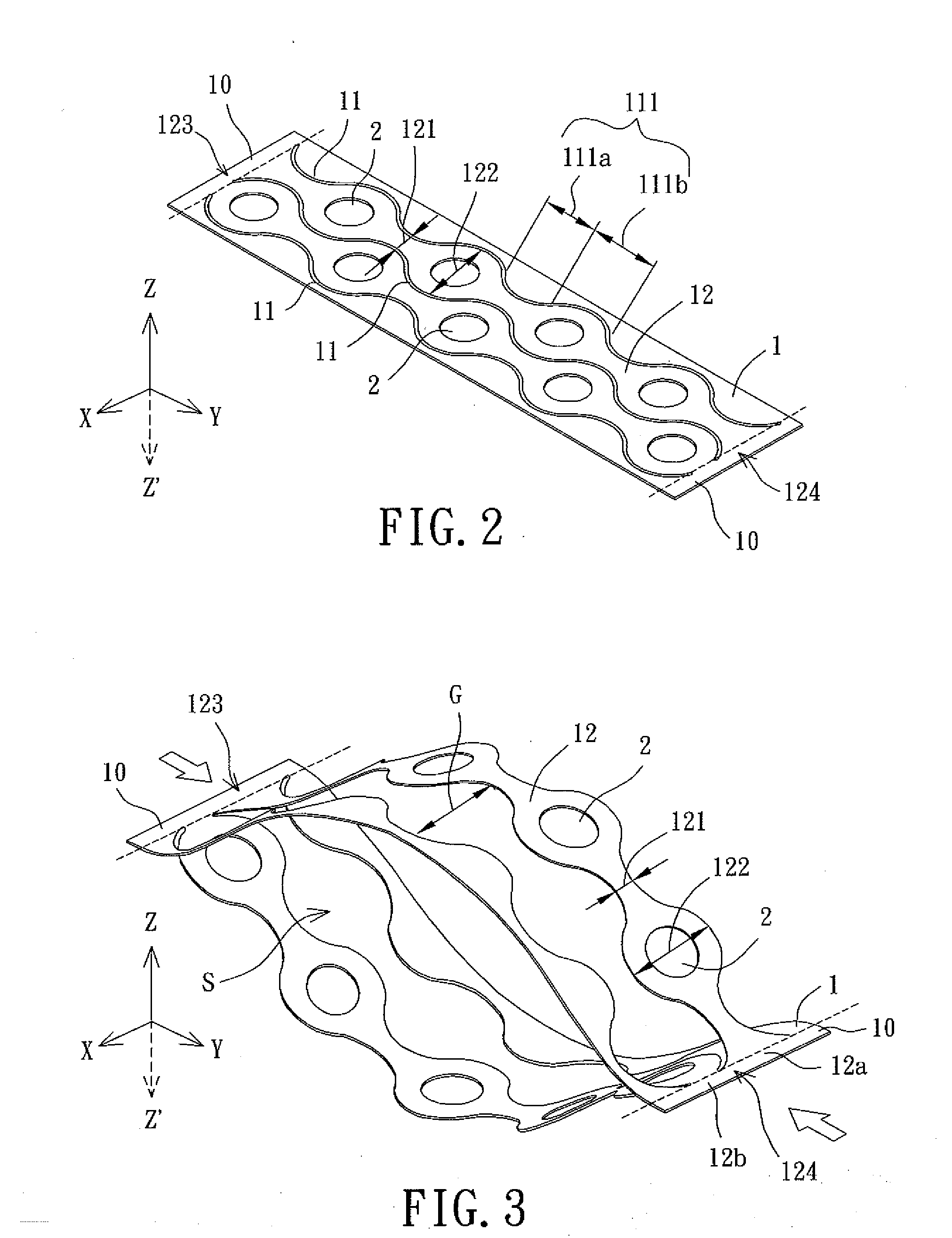
[0036]FIG. 2 shows an interbody cage according to a preferable embodiment of the invention, which includes a substrate 1 and a plurality of through holes 2. The plurality of through holes 2 penetrates the substrate 1 from one side of the substrate 1 to an opposite side thereof so as to communicate these two opposite sides of the substrate 1. The substrate 1 is preferably made of pure titanium or titanium alloy with a thickness of 20-200 micrometers between the two opposite sides, so that the substrate 1 is easy to be deformed into a specific shape during a medical operation.

[0037]The substrate 1 has two lateral bars 10 on two opposite ends of the substrate 1 and a plurality of curve slits 11 extending between the two lateral bars 10. Each of the curve slits 11 has a plurality of sections 111, wherein routes of the curve slits 11 in the sections 111 may be the same or different so as to form the sections 111 with repeated or random shapes. Specifically, each slit 11 of the substrate ...


PUM


Abstract

An interbody cage including a substrate and a plurality of through holes is disclosed. The substrate has a plurality of curve slits, with each of the curve slits having a plurality of sections, wherein a plurality deformable ribs is formed, with each deformable rib between any two curve slits and having a narrow part and a wide part. The plurality of through holes is formed in the wide part of the deformable rib. In use, any adjacent two of the deformable ribs are capable of being bent to depart from each other to define a filling room.

Description

BACKGROUND OF THE INVENTION[0001]1. Field of the Invention[0002]The present invention relates to an interbody cage and, more particularly, to an interbody cage for spine fusion, which is capable of enhancing the growing speed and stability of bones.[0003]2. Description of the Related Art[0004]Recently, cases of spinal diseases have occurred often since the numbers of office workers and the elders are increasing and the spinal diseases are common in these two groups. Therefore, how to take care of patients of spinal diseases has become more and more important.[0005]Generally, medical attention of a spinal patient after an operation is extremely important for the patient's recovery, and the patient usually has to put on a spinal brace for a long time so that the spinal brace may provide an external support for the spine of the patient and prevent the recovering spine from injury again.[0006]Nowadays, the way to improve the patient's recovery is to implant an interbody cage in a positi...

Claims


Application Information

Patent Timeline
IPC IPC(8): A61F2/44
CPCA61F2/4455A61F2310/00359A61B17/7065A61B2017/00004A61F2002/30018A61F2002/30064A61F2002/30136A61F2002/30148A61F2002/30153A61F2002/30433A61F2002/30509A61F2002/30578A61F2002/30607A61F2002/30616A61F2002/30777A61F2002/30784A61F2002/30785A61F2002/30787A61F2002/30828A61F2002/3097A61F2310/00023A61F2310/00293A61F2/447A61F2002/30014A61F2002/30507
Inventor SHIH, WEI-JENLYU, YU-TINGCHEN, WEI-TECHEN, YEN-NIEN
Owner METAL INDS RES & DEV CENT
Learn More