Saddle-ride type vehicle

Inactive Publication Date: 2013-06-20
HONDA MOTOR CO LTD
View PDF22 Cites 17 Cited by
  • Summary
  • Abstract
  • Description
  • Claims
  • Application Information

AI Technical Summary

Benefits of technology

[0047]Also, the air bubble return port is provided outside of the fuel collecting means, thereby preventing the entry of the air bubbles into the fuel collecting means through the air bubble return port and allowing the effective supply of fuel to the fuel suction port.
[0048]Moreover, since the fuel stored by the fuel collecting means elevated above the reservoir area can be supplied to the reservoir area, the effective supply of fuel can be performed even in a low remaining fuel condition.
[0049]Further, both of the fuel flowing into fuel collecting means through the opening and the fuel returned from

Problems solved by technology

Meanwhile, in saddle-ride type vehicles, the acceleration or deceleration of the vehicle exerts an influence upon the level of the fuel within the

Method used


Image

  • Saddle-ride type vehicle
  • Saddle-ride type vehicle
  • Saddle-ride type vehicle

Examples


first embodiment

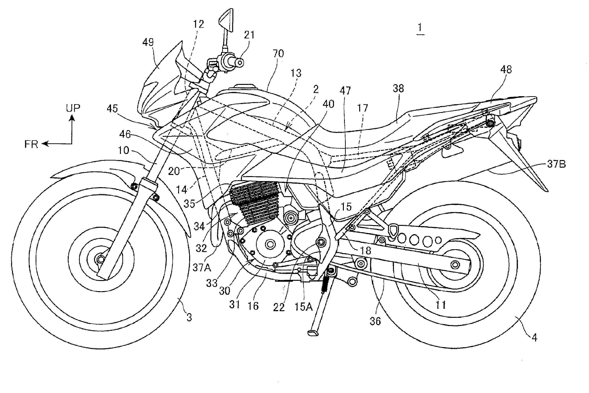
[0066]FIG. 1 is a left side view of a saddle-ride type vehicle according to the present invention.

[0067]As shown in FIG. 1, a motorcycle 1 (a saddle-ride type vehicle) is a saddle-ride type vehicle in which an engine 30 is disposed at the longitudinal center of a frame 2; a front fork 10 for supporting a front wheel 3 is steerably supported at a front end of the frame 2; and a swing arm 11 for supporting a rear wheel 4 is provided on a rear portion of the frame 2.

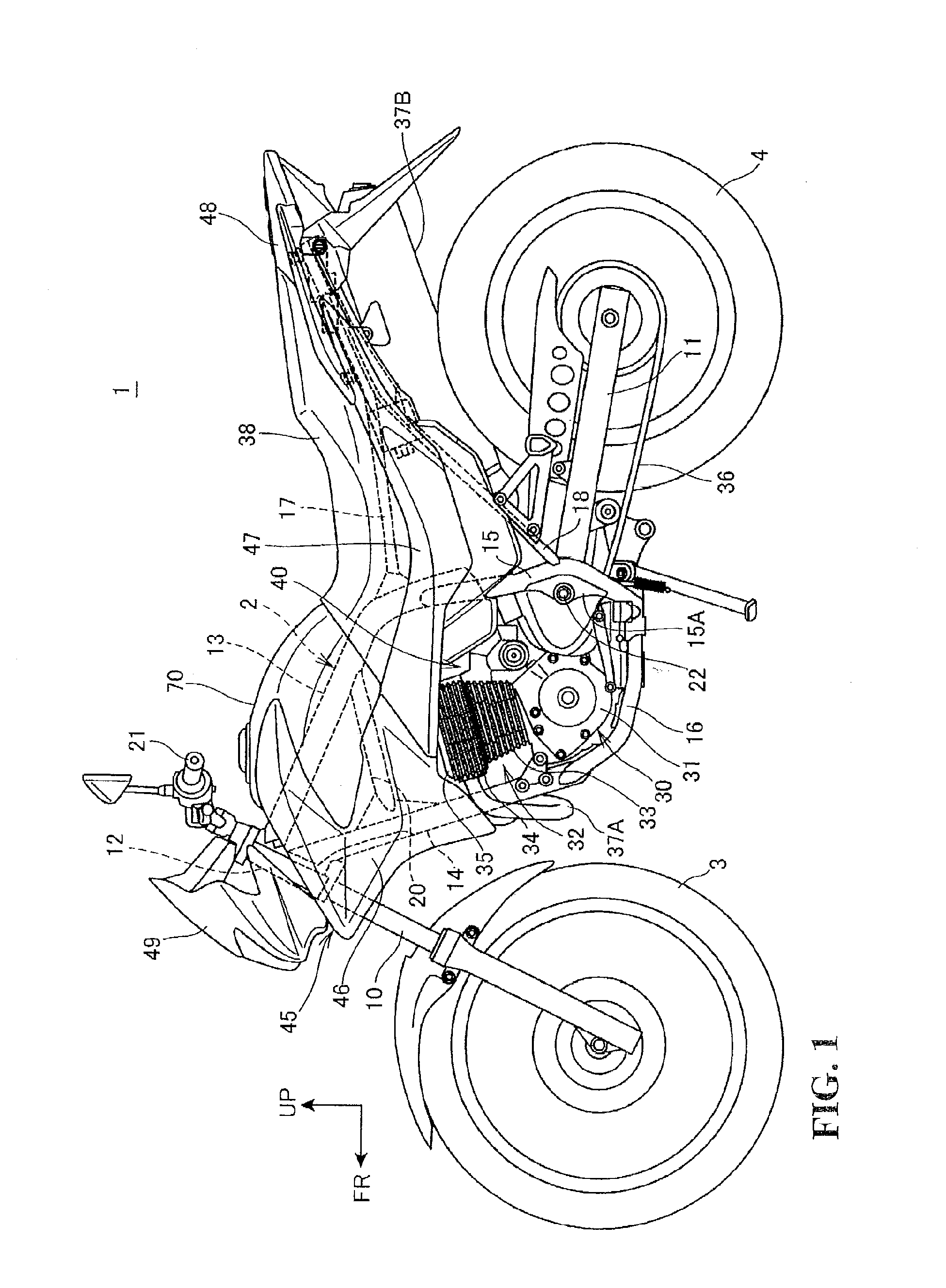
[0068]FIG. 2 is a left side view showing the frame 2 and its peripheral components. It is to be noted that, in FIG. 2, a crankcase of the engine 30 is not shown.

[0069]As shown in FIGS. 1 and 2, the frame 2 is composed of a head pipe 12 that is located at a front portion of a vehicle body; a single main frame 13 (a body frame) that is inclined to extend obliquely downward toward the rear from an upper portion of the head pipe 12; a single down frame 14 that is inclined to extend obliquely downward toward the rear from a lowe...

second embodiment

[0125]FIG. 9 is a left side view of the fuel tank 270 according to the

[0126]The fuel tank 270 fixed to the main frame 13 has the left and right side reservoir portions 72. Each of the side reservoir portions 72 has a side bottom plate portion 276 (a fuel tank bottom) constituting the bottom thereof. The side bottom plate portion 276 has the rear bottom plate portion 76A located above the throttle body 41 (FIG. 2), and a front bottom plate portion 276B located above the head cover 35 (FIG. 2). The lowermost end 79 of the side reservoir portion 72 is provided on the front bottom plate portion 276B, at a longitudinally intermediate portion of the fuel tank 270. The side bottom plate portion 276, forwardly of and to the rear of the lowermost end 79, is inclined downwardly toward the lowermost end 79.

[0127]The sub-chamber 89 is disposed such that the front wall 92A is located toward the lowermost end 79. The opening 94 in the rear wall 92B is disposed facing toward the vehicle front. The...

third embodiment

[0134]In the construction fuel is supplied to the engine 30 by the carburetor (not shown) in place of the throttle body 41 (FIG. 2). The above-described carburetor is disposed at the same location as the throttle body 41. Also, the fuel injection device 44 and the fuel pump 50 are not disposed.

[0135]FIG. 10 is a side view showing a connection of the fuel cock 386 of a fuel tank 370 according to the third embodiment.

[0136]The fuel tank 370 fixed to the main frame 13 has the left and right side reservoir portions 72. Each of the side reservoir portions 72 has the side bottom plate portion 76 constituting the bottom thereof.

[0137]The rear bottom plate portion 76A of the side bottom plate portion 76 is provided with the fuel cock 386 that sucks the fuel in the fuel tank 370 to feed it to the carburetor. The rear bottom plate portion 76A is also provided with the sub-chamber 89.

[0138]The fuel cock 386 has a suction pipe 387 that protrudes inwardly of the side reservoir portion 72; and a...


PUM


Abstract

To enable the effective supply of fuel in a low remaining fuel condition, even in a saddle-ride vehicle with a requirement for an increased fuel tank capacity being provided within a limited amount of space. The saddle-ride vehicle includes an engine having a cylinder disposed on a crankcase; an intake system component disposed at the rear of the cylinder for sucking air into the engine; and a fuel tank disposed above the engine for storing fuel. The saddle-ride type vehicle includes a fuel suction port in a side bottom plate portion of the fuel tank for feeding fuel to the intake system component. The saddle-ride vehicle has a sub-chamber having a wall that surrounds the fuel suction port and the sub-chamber includes a fuel flow opening toward the vehicle rear.

Description

CROSS-REFERENCE TO RELATED APPLICATIONS[0001]The present application claims priority under 35 USC 119 to Japanese Patent Application No. 2011-274231 filed Dec. 15, 2011 and Japanese Patent Application No. 2012-107297 filed May 9, 2012 the entire contents of which are hereby incorporated by reference.BACKGROUND OF THE INVENTION[0002]1. Field of the Invention[0003]The present invention relates to a saddle-ride type vehicle with a fuel tank disposed above an engine.[0004]2. Description of Background Art[0005]A sub-chamber of a fuel tank is known wherein the fuel tank is improved to effectively suck up fuel even if a low remaining fuel condition exists within the fuel tank. The fuel tank may be inclined relative to a vehicle body. See, for example, JP-A No. H11-321355. With the construction according to the JP-A No. H11-321355, when the fuel tank is in an inclined position, the fuel suction capacity of a pipe for sucking the fuel from the sub-chamber can be increased by upwardly inclini...

Claims


Application Information

Patent Timeline
IPC IPC(8): B60K15/03
CPCB60K15/03006B62J37/00B62J35/00F02M37/007F02M37/0094F02B61/00F02M37/46F02M37/22
Inventor KAWANO, SUNAONAKANO, MASATAKAHARA, IKUOSHIMURA, TAKESHIHIGASHIYAMA, JUNJI
Owner HONDA MOTOR CO LTD
Why Eureka
Try Eureka