Temperature Modulated Refractive Index Measurement

a refractive index and temperature-modulated technology, applied in the direction of phase-affecting property measurement, measurement device, instruments, etc., can solve the problems of unsuitable samples underlying, method cannot be used for liquid samples, and undesirable to have different temperatur

Active Publication Date: 2013-06-20
ANTON PAAR OPTOTEC
View PDF4 Cites 8 Cited by
  • Summary
  • Abstract
  • Description
  • Claims
  • Application Information

AI Technical Summary

Benefits of technology

[0022]In another preferred embodiment the method further comprises the steps of providing a plot of the refractive index versus the time and/or modulation frequency of temperature; and/or providing a plot of the temperature coefficient of the refractive index versus the time and/o

Problems solved by technology

Unfortunately, this method can only be used for liquid samples.
Furthermore, the method is unsuitable for samples underlying a chemical reaction which necessitates a constant temperature extending over the whole sample.
Especially in the case of chemical reactions it is often undesirable to have different temperature across the sample because this might strongly influence the complete reaction and/or might induce c

Method used


Image

  • Temperature Modulated Refractive Index Measurement
  • Temperature Modulated Refractive Index Measurement
  • Temperature Modulated Refractive Index Measurement

Examples


Embodiment Construction

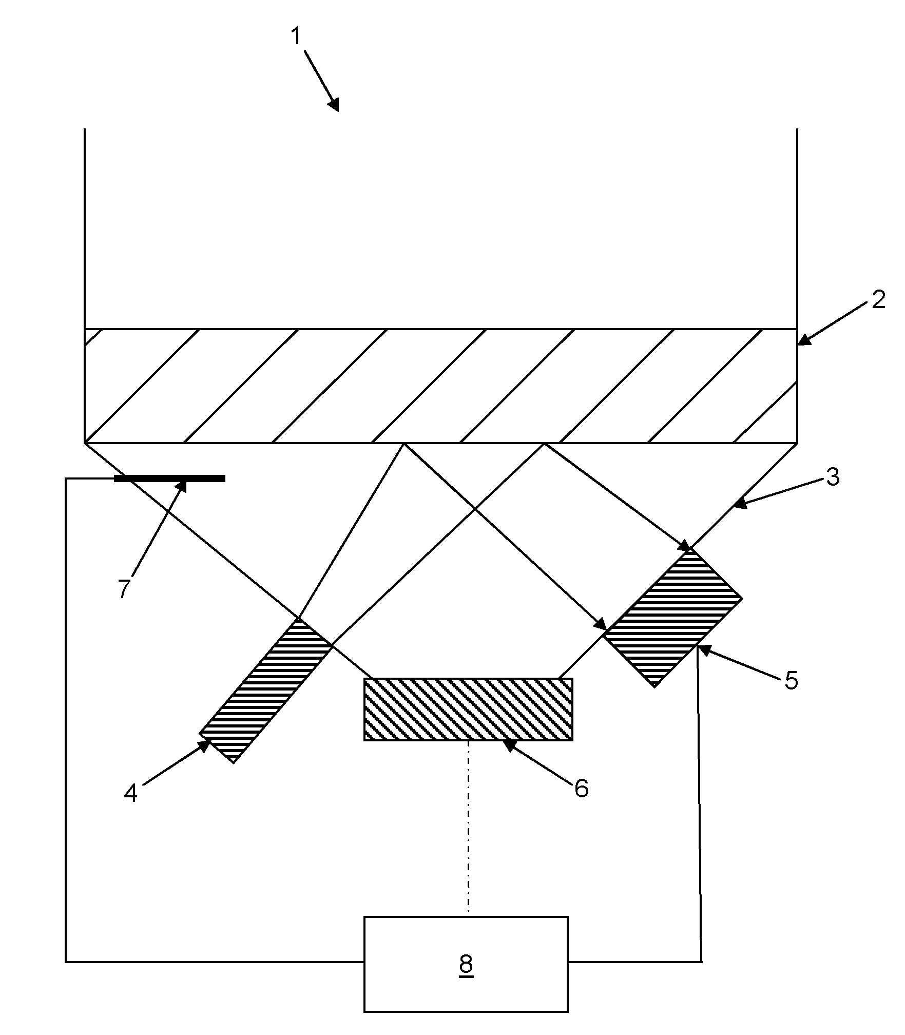
[0034]FIG. 1 depicts a scheme of a refractometer 1. A sample 2 is adjoining a prism 3 either in direct contact with each other or in indirect contact via a suitable immersion liquid. Furthermore, the setup of FIG. 1 includes a light source 4 generating a light beam positioned at a first side of the prism 1. The light source 4 is further arranged such that light is guided through the prism 3 onto the sample 2 at the interface between sample 2 and the prism 3, i.e. a second side of the prism 3. At least a part of the light beam is reflected through the prism 3 back to a light detector 5 which is arranged at a third side of the prism 3. Preferably, the light beam has optical wavelengths though other frequencies may be used as well. The refractometer 1 further comprises a temperature control system 6, preferably adapted to control the temperature of the sample 2 and preferably of the prism 3. The temperature control system 6 may further comprise a temperature sensor system 7 allowing fo...


PUM


Abstract

The present invention is directed to temperature modulated refractive index measurement. In accordance with the invention a method for determination of the complex temperature coefficient of the refractive index of a sample is provided, wherein the determination of the complex temperature coefficient of the refractive index of the sample is based on a refractive index measurement. Furthermore, the refractive index of the sample is measured over a period of time, wherein the temperature of the sample is modulated over said period of time and the complex temperature coefficient of the refractive index is calculated on the basis of the refractive index measurement over the period of time and the temperature modulation over the period of time. Additionally, a measurement system, in particular comprising a temperature control system and a processing system to carry out the above method, is disclosed.

Description

CROSS-REFERENCE TO RELATED APPLICATIONS [0001]The present invention is the US national stage under 35 U.S.C. §371 of International Application No. PCT / EP2011 / 063311, which was filed on Aug. 2, 2011 and which claims the priority of application LU 91723 filed on Aug. 23, 2010 the content of which (text, drawings and claims) is incorporated here by reference in its entirety.TECHNICAL FIELD [0002]The present invention is directed to refractive index measurement and to the determination of the temperature coefficient of the refractive index.BACKGROUND OF THE INVENTION[0003]Multiple methods as well as respective devices for measuring the refractive index of samples are known in the state of the art. Especially refractometry is used for measurement of the refractive index. For instance an Abbe refractometer can be used to measure the refractive index of a sample. Such a refractometer comprises a prism adjoining a sample and a light source being arranged to generate a beam of light travelli...

Claims


Application Information

Patent Timeline
IPC IPC(8): G01N21/41
CPCG01N21/41G01N2021/1731G01N21/43G01N2201/0691
Inventor MULLER, ULRICHKRUGER, JAN KRISTIAN
Owner ANTON PAAR OPTOTEC
Why Eureka
Try Eureka