
Server structure with swappable tray

a server and tray technology, applied in the field of industrial computers, can solve the problems of inconvenient use on one side of the server, inability to freely replace motherboards and hard drives with different specifications, and the server is usually turned on for a long time, so as to improve the functionality and convenience of the server structure, facilitate customers' management, and reduce manufacturing costs

Active Publication Date: 2013-06-20
SUPER MICRO COMP
View PDF9 Cites 17 Cited by
  • Summary
  • Abstract
  • Description
  • Claims
  • Application Information

AI Technical Summary

Benefits of technology

The present invention is a server structure with a swappable tray, which allows users to easily replace the motherboard tray to meet different needs. The motherboard tray can be plugged into any position, creating a swappable tray. The server structure also has hot swapping function, meaning users can easily replace the motherboard or storage unit set without shutting down the server. The same mold can be used to manufacture the motherboard trays, reducing manufacturing costs. The server structure also has improved flexibility, with options for different server positions and easy installation, maintenance, or repair of the storage unit set. Additionally, the server structure has a large storage space and is convenient to users. The flexible pulling ring made of rubber also provides improved convenience.

Problems solved by technology

In general, a server is usually turned on for a long time, and companies usually require maintaining, repairing or replacing a hardware component without turning off the server system when any hardware component of the server system breaks down.
As a result, the motherboard and the hard disk cannot be replaced freely by those with a different specification to meet different application requirements.
In addition, the motherboard and the hard disk are installed on both sides of the central back panel, so that use on one side of the server is inconvenient for users to plug or unplug the motherboard or the hard disk, and the functions and effects of using the server are limited.

Method used


Image

  • Server structure with swappable tray
  • Server structure with swappable tray
  • Server structure with swappable tray

Examples


Embodiment Construction

[0016]The technical characteristics and contents of the present invention will become apparent with the following detailed description and related drawings. The drawings are provided for the purpose of illustrating the present invention only, but not intended for limiting the scope of the invention.

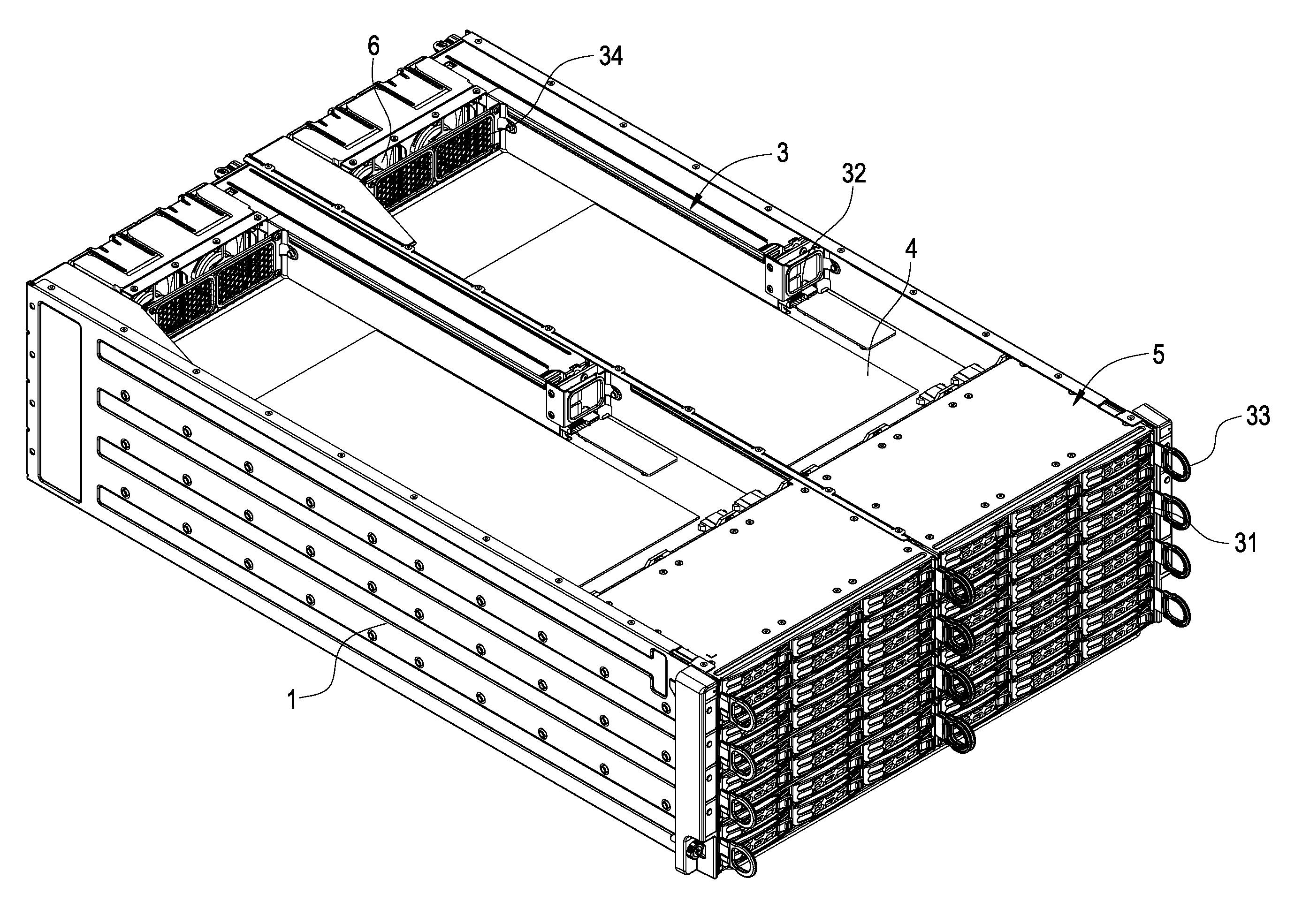
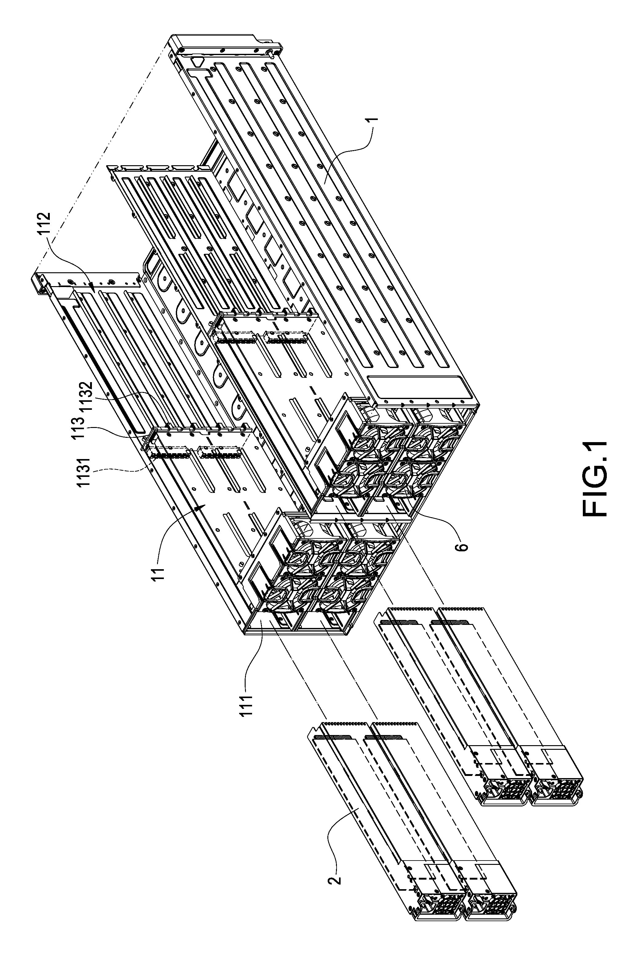
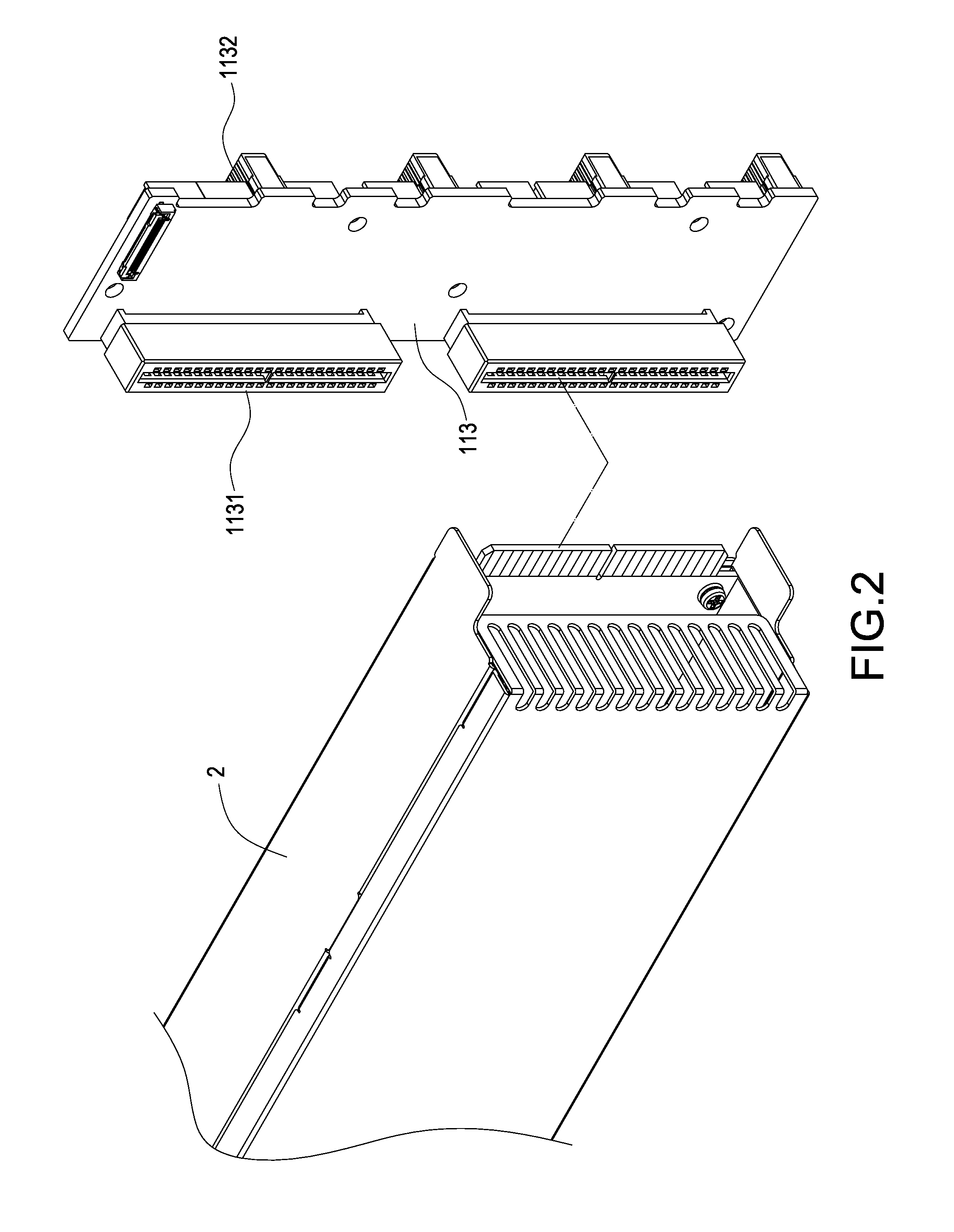
[0017]With reference to FIGS. 1 to 8 for a server structure with a swappable tray in accordance with the present invention, the server structure comprises a chassis housing 1, two power supply devices 2 and a plurality of motherboard trays 3.

[0018]The chassis housing 1 includes at least two parallel motherboard areas 11, wherein the chassis housing 1 of a preferred embodiment as shown in FIG. 1 has two parallel rows of four motherboard areas 11, and each motherboard area 11 has a power slot 111 formed at a rear section of each motherboard area 11 and a plurality of tray slots 112 formed at a front section of each motherboard area 11, and the power slots 111 are formed separately at the sa...


PUM


Abstract

A server structure with a swappable tray includes a chassis housing, two power supply devices and a plurality of motherboard trays, and the chassis housing has two parallel motherboard areas, and each motherboard area has a power slot formed at a rear section and a plurality of tray slots at a front section, and each power slot is formed at the same position of each motherboard area, and each power supply device is plugged into each respective power slot, and each motherboard tray is in the same shape and has a motherboard, and each motherboard tray has an opening and a storage unit set installed through the opening, and each motherboard tray can be swapped and plugged into any one of the tray slots. Therefore, the motherboard tray can be installed freely at any position according to the using requirement, so as to improve the overall functionality and convenience.

Description

FIELD OF THE INVENTION[0001]The present invention relates to an industrial computer, in particular to a server structure with a swappable tray applied in a server.BACKGROUND OF THE INVENTION[0002]As the computer industry advances, companies rely more and more on industrial computer systems, and corporate requirements of a server system become increasingly higher. To cope with the growth of a company, many companies integrate a number of servers to satisfy the requirements for huge data volume and network flow and allow expansions and updates of the server system in the future.[0003]In general, a server is usually turned on for a long time, and companies usually require maintaining, repairing or replacing a hardware component without turning off the server system when any hardware component of the server system breaks down. Therefore, a conventional plug-in server is introduced, wherein the design of a single central back panel is provided for connecting separate hard disk area, moth...

Claims


Application Information

Patent Timeline
Patent Type & Authority Applications(United States)
IPC IPC(8): G06F1/16H05K7/20H05K7/14
CPCH05K7/1489G06F1/181G06F1/187G06F1/183H05K7/1492
Inventor LIN, TE-CHANG
Owner SUPER MICRO COMP
Learn More