High power micro-speaker

a micro-speaker, high-power technology, applied in the direction of deaf-aid sets, electrical transducers, electrical equipment, etc., can solve the problems of limiting the design of a high-power slim micro-speaker, reducing the vibrating region required for vertical movement of the voice coil, and limiting the acquisition of high power or small thickness, so as to facilitate the automation of fabrication and simplify the successive assembly process. , the effect of a larger vibrating region

Inactive Publication Date: 2013-06-20
BUJEON
View PDF0 Cites 46 Cited by
  • Summary
  • Abstract
  • Description
  • Claims
  • Application Information

AI Technical Summary

Benefits of technology

[0015]It is another object of the present invention to provide a micro-speaker which ensures a simplified successive assembly process, thereby achieving ease in automation of fabrication.
[0016]It is another object of the present invention to provide a micro-speaker in which a voice coil is attached to a lower surface of a vibrating plate, more particularly, to a lower surface of a center dome part of the vibrating plate located above a damper plate, rather than being attached to a lower surface of the damper plate, which can provide a larger vibrating region required for vertical vibration of the voice coil.
[0017]It is another object of the present invention to provide a micro-speaker in which a damper plate is provided with an opening, through which a voice coil can pass, and the voice coil having passed through the opening is attached to a lower surface of a vibrating plate, more particularly, to a lower surface of a center dome part of the vibrating plate that is located above the damper plate, whereby an available space equivalent to a thickness of the damper plate is acquired and a height of the voice coil or a magnet can be increased as much as a height of the acquired space, resulting in a high power of the micro-speaker.
[0018]It is another object of the present invention to provide a micro-speaker, in which a damper plate is provided with an opening, through which a voice coil can pass, and the voice coil having passed through the opening is attached to a lower surface of a vibrating plate, more particularly, to a lower surface of a center dome part of the vibrating plate that is located above the damper plate, whereby an available space equivalent to a thickness of the damper plate is acquired and a height of a frame can be reduced as much as a height of the acquired space, resulting in a slim design of the micro-speaker.
[0019]It is another object of the present invention to provide a micro-speaker in which a damper plate is provided with an opening, through which a voice coil can pass, and the voice coil having passed through the opening is attached to a lower surface of a vibrating plate, more particularly, to a lower surface of a center dome part of the vibrating plate that is located above the damper plate such that an adhesive or adhesive residue applied between an upper surface of the voice coil and the vibrating plate has a thickness equal to or less than a thickness of the damper plate, which can prevent a reduction in a vibrating region and provide a high power slim micro-speaker.
[0020]It is a further object of the present invention to provide a micro-speaker and a method of fabricating the same, in which a damper plate is provided with an opening, through which a voice coil can pass, and a lead wire of the voice coil is attached to an upper surface of the damper plate by passing through the opening, whereby the voice coil can be vertically attached to the damper plate, and ease in automation of an assembly process can be accomplished.

Problems solved by technology

However, a height of an adhesive residue (pellets) on a lateral surface of the voice coil 30 as well as the thickness t of the applied adhesive 95 may disadvantageously reduce the vibrating region A required for vertical movement of the voice coil 30.
This results in a limit to acquisition of a high power or small thickness.
This consequently limits design of a high power slim micro-speaker.
As a result, the conventional micro-speaker 1A suffers from complexity and automation difficulty in fabrication.

Method used


Image

  • High power micro-speaker
  • High power micro-speaker
  • High power micro-speaker

Examples


Embodiment Construction

[0041]Hereinafter, a high power micro-speaker according to the present invention will be described in more detail with reference to the accompanying drawings. In the following description of the present invention, the same constituent elements as those of the previously described conventional micro-speaker will be designated by the same reference numerals, and a detailed description thereof will be omitted.

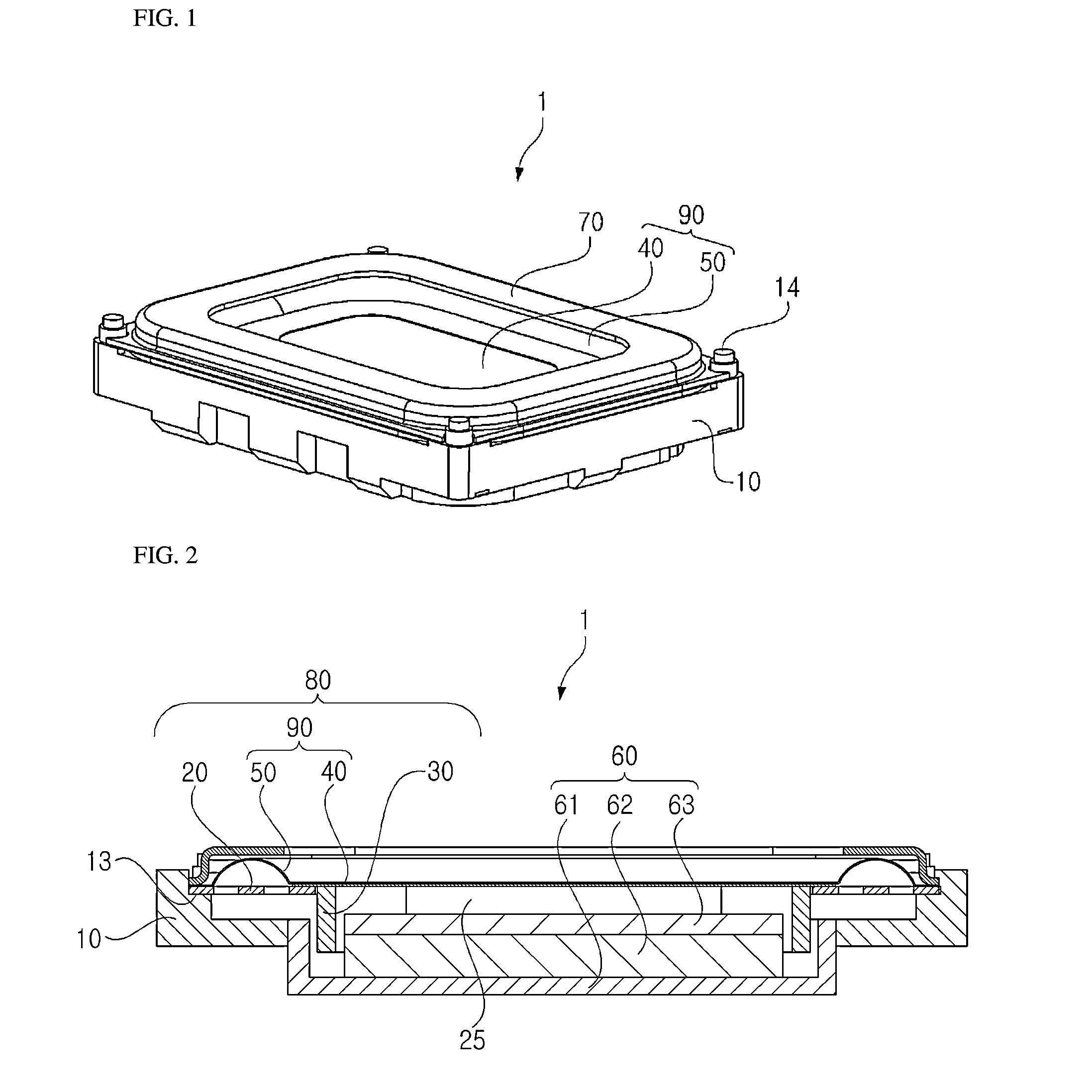
[0042]FIGS. 1 and 2 illustrate an embodiment of a high power micro-speaker (hereinafter briefly referred to as a ‘micro-speaker’) according to the present invention.

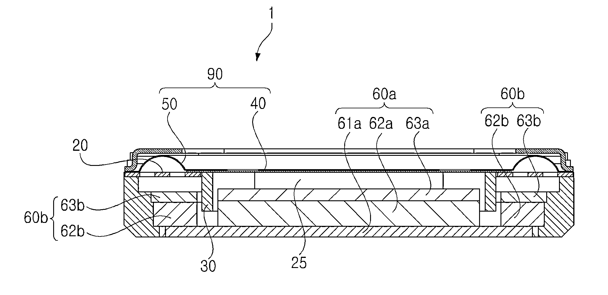
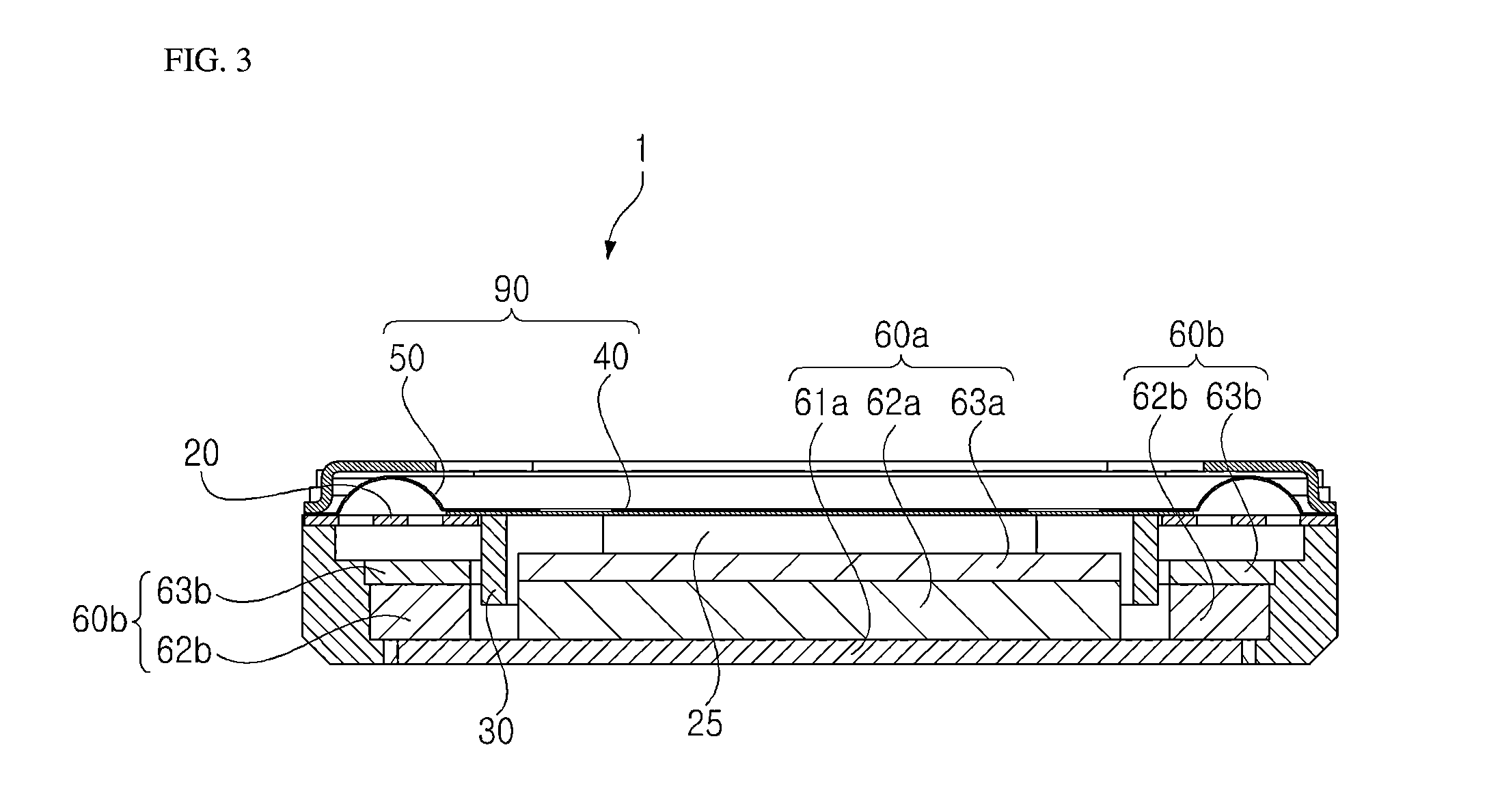
[0043]As illustrated in the drawings, the micro-speaker, designated by reference numeral 1, according to the present invention includes a frame 10 having a small thickness. The frame 10 is vertically perforated to have open upper and lower ends. Accommodated in the frame 10 are a vibrating plate 90, a voice coil 30, and a magnetic field generator 60 that consists of an upper plate 63, a magnet 62, and a lower plate 61....


PUM


Abstract

Disclosed is a high power micro-speaker having a damper plate. More particularly, disclosed is a high power micro-speaker in which a damper plate has an opening through which a voice coil can pass, and the voice coil having passed through the opening is attached to a lower surface of a vibrating plate that is located above the damper plate, which provides an increased vibrating region. As such, enhanced output power of the micro-speaker is accomplished by increasing a height of the voice coil, or a slimmer design of the micro-speaker is accomplished by reducing a height of a frame.

Description

BACKGROUND OF THE INVENTION[0001]1. Field of the Invention[0002]The present invention relates to a high power micro-speaker having a damper plate, and more particularly to a high power micro-speaker in which a damper plate has an opening through which a voice coil can pass, and the voice coil having passed through the opening is attached to a lower surface of a vibrating plate that is located above the damper plate, which provides an increased vibrating region, whereby a height of the voice coil may be increased to enhance power, or a height of a frame may be reduced to achieve a slimmer design of the micro-speaker.[0003]2. Description of the Related Art[0004]In general, portable electronic appliances, such as portable mobile communication terminals, laptop computers, MP3 players, and earphones, for example, are equipped with micro-speakers that convert an electric signal into a sound signal.[0005]Considering a configuration of conventional micro-speakers, a magnetic circuit is cons...

Claims


Application Information

Patent Timeline
Patent Type & Authority Applications(United States)
IPC IPC(8): H04R9/06
CPCH04R9/06H04R2499/11H04R31/00H04R9/045H04R3/002H04R7/18H04R9/04
Inventor KIM, SUNG SIK
Owner BUJEON
Why Eureka
Try Eureka