Reactive gas shroud or flame sheath for suspension plasma spray processes

a plasma spray and reactive gas technology, applied in the field of suspension plasma sprays, can solve the problems of increasing the likelihood of clogging in the conventional powder feed system, limiting the use of particles in the technology, and increasing the difficulty of introducing powdered coating material directly into the plasma jet, so as to improve the fragmentation of suspension droplets

Inactive Publication Date: 2013-06-20
PRAXAIR ST TECH INC
View PDF2 Cites 10 Cited by
  • Summary
  • Abstract
  • Description
  • Claims
  • Application Information

AI Technical Summary

Benefits of technology

[0011]As described in more detail below, the present embodiments of the invention addresses some of the disadvantages and provides techniques to control the aforementioned interactions through use of a reactive gas shroud surrounding the plasma effluent stream and liquid suspension contained therein (collectively, referred to as “effluent,”“effluent stream,”“plasma,” or “plasma effluent,” or “plasma effluent stream” herein and throughout the specification). The present invention uniquely combines a reactive gas shroud with a plasma spray process using submicron particles delivered via liquid suspension to improve current suspension plasma spray capabilities and create new coating microstructure possibilities through controlling the suspension injection and fragmentation as well as the interactions between the effluent and suspensions.
[0014]The present invention may also be characterized as a method of producing coatings on a substrate using a liquid suspension with sub-micron particles dispersed therein, the method comprising the steps of: generating a plasma from a thermal spray torch; delivering a flow of liquid suspension with sub-micron particles dispersed therein to the plasma or in close proximity thereto to produce a plasma effluent stream; surrounding the plasma effluent with a reactive gas shroud to keep the sub-micron particles entrained within the plasma effluent and substantially prevent entrainment of ambient gases into the plasma effluent; reacting the shroud gas with the plasma effluent to enhance fragmentation of the suspension droplets and create evaporative species of the sub-micron particles within the plasma effluent; and directing the shrouded plasma effluent with the sub-micron particles contained therein towards the substrate to coat the substrate.

Problems solved by technology

However, this technology is typically limited to the use of particles of at least +350 mesh (i.e., a median particle size of approximately of 45 microns in which 50 percent of particles are smaller than the median size and the other 50 percent of the particles are larger than the median size) or larger.
As particle size decreases below +325 mesh, introducing powdered coating material directly into the plasma jet becomes progressively more difficult.
Fine particles tend to pack tightly and agglomerate, increasing the likelihood of clogging in conventional powder feed systems.
In addition to clogging, conventional plasma spray technology is also ill-suited to the use of fine particles for other reasons.
Practical limitations exist to increase velocity to this degree.
Notwithstanding the improvements of SPS over conventional plasma spray technology, current SPS systems and processes continue to suffer from a variety of drawbacks.
For instance, conventional SPS typically produce coatings having uncontrolled microstructure grain size and / or lack of directional orientation growth, both of which can result in poor coating properties.
To further compound the microstructural problem, adverse chemical reactions can occur between the substrate and the deposited coating materials.
Further, longer stand-off distances between the nozzle location and the deposition point may be required to adequately coat complicated geometries such as turbine blades.
However, the longer stand-off distances may provide the coating constituents excessive dwell or residence time, thereby causing cooling and resolidifcation of coating constituents prior to reaching the substrate.
Reducing the stand-off distance can cause insufficient heating such that the particulates are never able to absorb enough heat and fully melt.
In both cases, the end result is lack of particulate adhesion to the substrate, thereby reducing deposition efficiency of the material.
Accordingly, the increased surface area of the finer particulates creates unprecedented challenges to optimizing the correct stand-off distance.
As a result, the ejected particulates result in decreased deposition efficiency.
The above problems are only a few examples of the types of new challenges posed by the utilization of SPS systems and processes to deposit ever increasingly finer coating media constituents.

Method used


Image

  • Reactive gas shroud or flame sheath for suspension plasma spray processes
  • Reactive gas shroud or flame sheath for suspension plasma spray processes
  • Reactive gas shroud or flame sheath for suspension plasma spray processes

Examples


Embodiment Construction

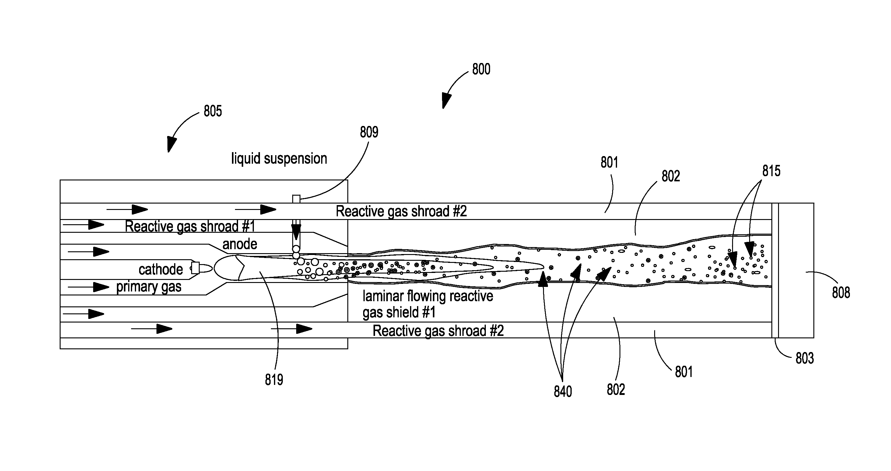
[0027]The present disclosure relates to a novel SPS system and process for the deposition of coating material. The SPS system and process of the present invention is particularly suitable for deposition of sub-micron particles. The disclosure is set out herein in various embodiments and with reference to various aspects and features of the invention.

[0028]The relationship and functioning of the various elements of this invention are better understood by the following detailed description. The detailed description contemplates the features, aspects and embodiments in various permutations and combinations, as being within the scope of the disclosure. The disclosure may therefore be specified as comprising, consisting or consisting essentially of, any of such combinations and permutations of these specific features, aspects, and embodiments, or a selected one or ones thereof.

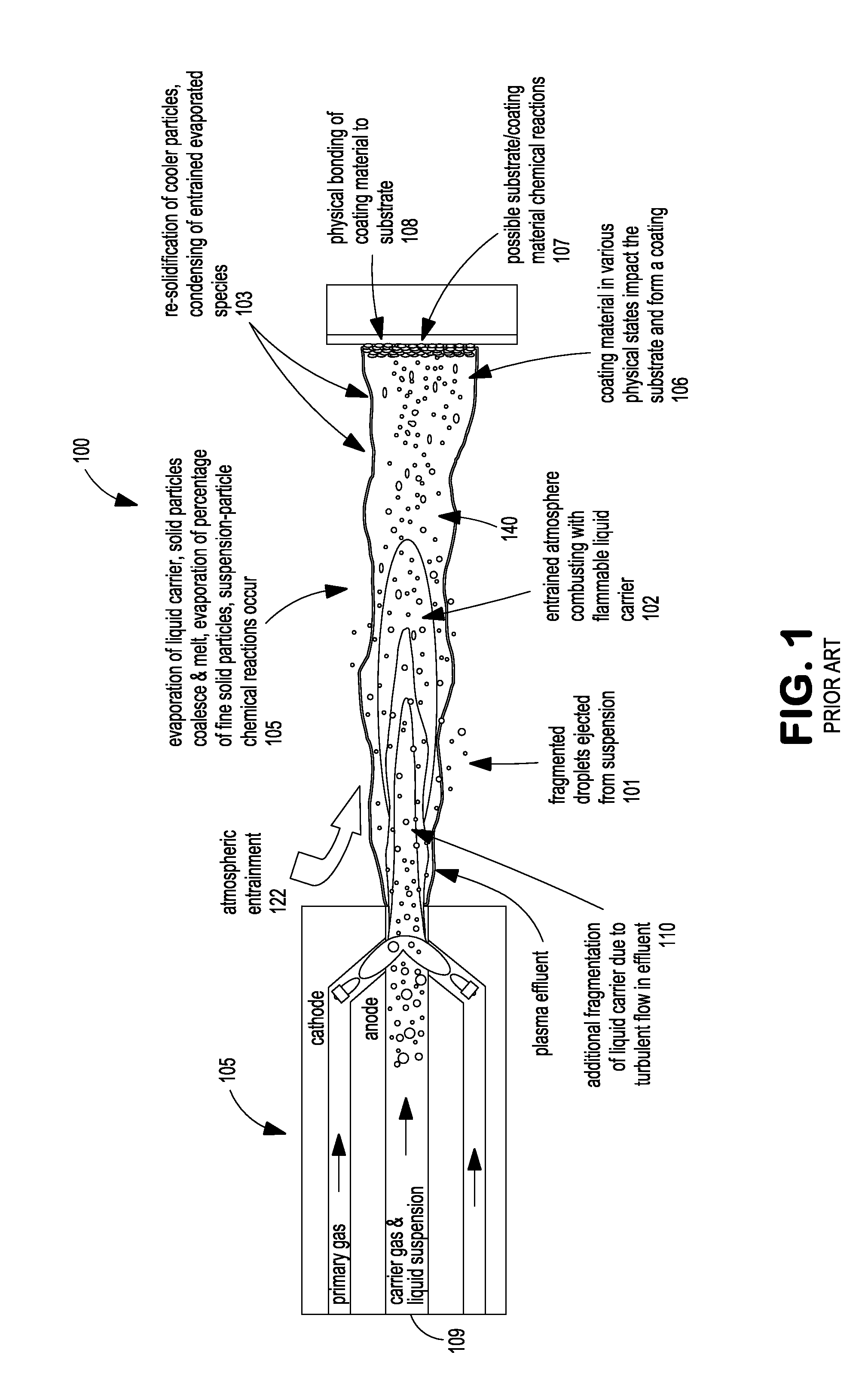
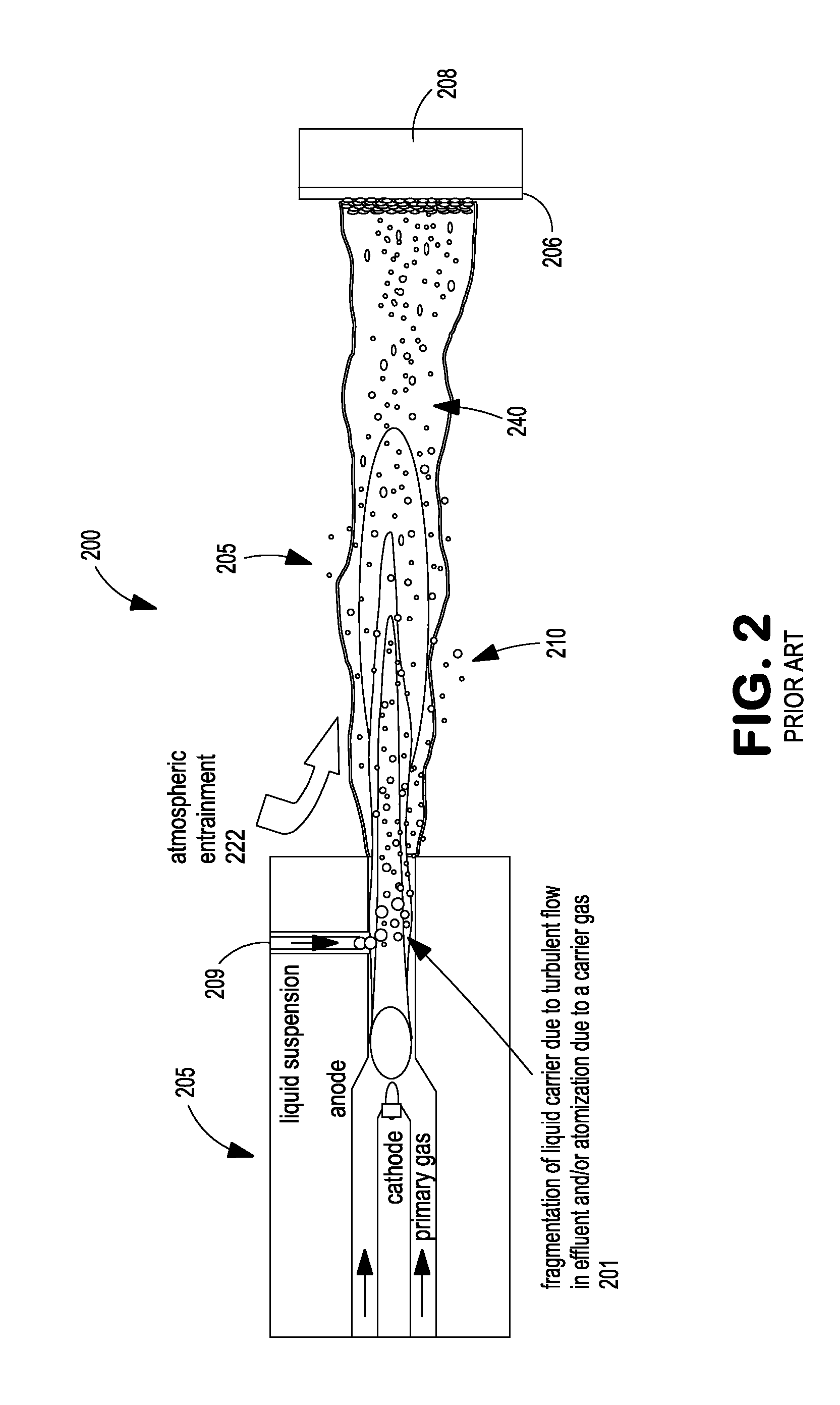
[0029]The present invention recognizes the shortcomings of current SPS systems and processes. These shortcomings...


PUM

PropertyMeasurementUnit
particle sizeaaaaaaaaaa
axial distanceaaaaaaaaaa
distanceaaaaaaaaaa

Abstract

A system and method for producing thermal spray coatings on a substrate from a liquid suspension is disclosed. The disclosed system and method include a thermal spray torch for generating a plasma and a liquid suspension delivery subsystem for delivering a flow of liquid suspension with sub-micron particles to the plasma to produce a plasma effluent. The liquid suspension delivery subsystem comprises an injector or nozzle which can produce a reactive gas shroud surrounding the plasma effluent. A flame envelope can also be used to isolate injection of the liquid suspension. The shroud or flame envelope can retain the sub-micron particles entrained within the plasma effluent and substantially prevent entrainment of ambient gases into the plasma effluent. The liquid suspension delivery subsystem can be arranged as an axial injection system, a radial internal injection system or an external radial injection system.

Description

[0001]The present application claims priority from U.S. application Ser. No. 61 / 570,532, filed Dec. 14, 2011, which is incorporated by reference herein in its entirety, and U.S. application Ser. No. 61 / 570,516, filed Dec. 14, 2011, which is incorporated by reference herein in its entirety.FIELD OF INVENTION[0002]The present invention relates to suspension plasma sprays, and more particularly to methods and systems for the shrouding of suspension plasma spray effluents and / or sheathing the injection of liquid suspensions using a reactive gas and / or flame envelope to facilitate and control the effluent and suspension interactions.BACKGROUND[0003]Conventional plasma spray technology primarily uses powder feeders to deliver powdered coating material into a plasma jet of a plasma spray gun. However, this technology is typically limited to the use of particles of at least +350 mesh (i.e., a median particle size of approximately of 45 microns in which 50 percent of particles are smaller th...

Claims


Application Information

Patent Timeline
Patent Type & Authority Applications(United States)
IPC IPC(8): C23C4/12
CPCC23C4/127C23C4/134
Inventor PETORAK, CHRISTOPHER A.LEMEN, DON J.FEUERSTEIN, ALBERTLEWIS, III, THOMAS F.
Owner PRAXAIR ST TECH INC
Why Eureka
Try Eureka