
Thermosiphon cooling system and method

a cooling system and superconducting magnet technology, applied in the field of magnetic resonance imaging (mri) systems, can solve the problems of increasing the running cost of the mri system, superconducting magnets may be subject to different heat loads, and the arrangement is not only expensive to manufacture, but also heavy to transpor

Active Publication Date: 2013-06-27
GENERAL ELECTRIC CO
View PDF18 Cites 20 Cited by
  • Summary
  • Abstract
  • Description
  • Claims
  • Application Information

AI Technical Summary

Benefits of technology

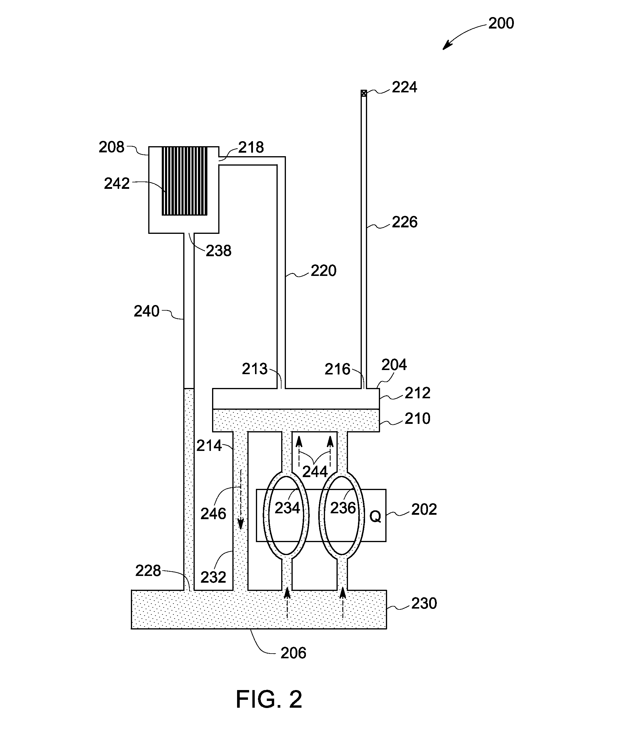
The present patent text describes a thermosiphon cooling system for cooling a superconducting unit that generates heat. The system includes a reservoir that stores a liquid coolant, and a tubing unit that receives the coolant from the reservoir and circulates it to dissipate the heat generated by the superconducting unit. The coolant is circulated by varying its density at different portions of the tubing unit. This cooling system can efficiently and effectively cool the superconducting unit, which can help to prolong its lifespan and improve its performance. The system can be provided as a kit for easy installation and maintenance.

Problems solved by technology

This constant supply of electric current to the superconducting magnet increases the running cost of the MRI system.
Furthermore, in certain other techniques, the superconducting magnet may be subjected to different heat loads in the MRI system.
Since this arrangement employs a large vessel with thousands of liters of liquid He, the arrangement is not only expensive to manufacture, but also heavy to transport and install at a desired location, such as, diagnostic centers.
Additionally, the refill of thousands of liters of liquid He for delivery to remote locations may be inconvenient.
Moreover, the liquid He in these systems can sometimes boil-off during a quench event.
Thus, each quench event is followed by re-filling of the liquid He and re-ramping of the magnet, which is an expensive and time consuming event.
However, the venting pipes are difficult to install.
Also, in some situations, the venting of He can have environmental or regulatory concerns.
Thus, conventional MRI magnet designs and their cooling arrangements can entail special installation requirements, the inability to install these systems in certain regions, and a high maintenance cost.

Method used


Image

  • Thermosiphon cooling system and method
  • Thermosiphon cooling system and method
  • Thermosiphon cooling system and method

Examples


Embodiment Construction

[0018]As will be described in detail hereinafter, various embodiments of an exemplary thermosiphon cooling system and methods for cooling superconducting magnets / coils are presented. By employing the methods and the various embodiments of the thermosiphon cooling system described hereinafter, volume of liquid coolant, size of the magnetic devices, cost of manufacturing, cost of installing, and cost of running the magnetic devices, such as magnetic resonance imaging (MRI) systems may be substantially reduced.

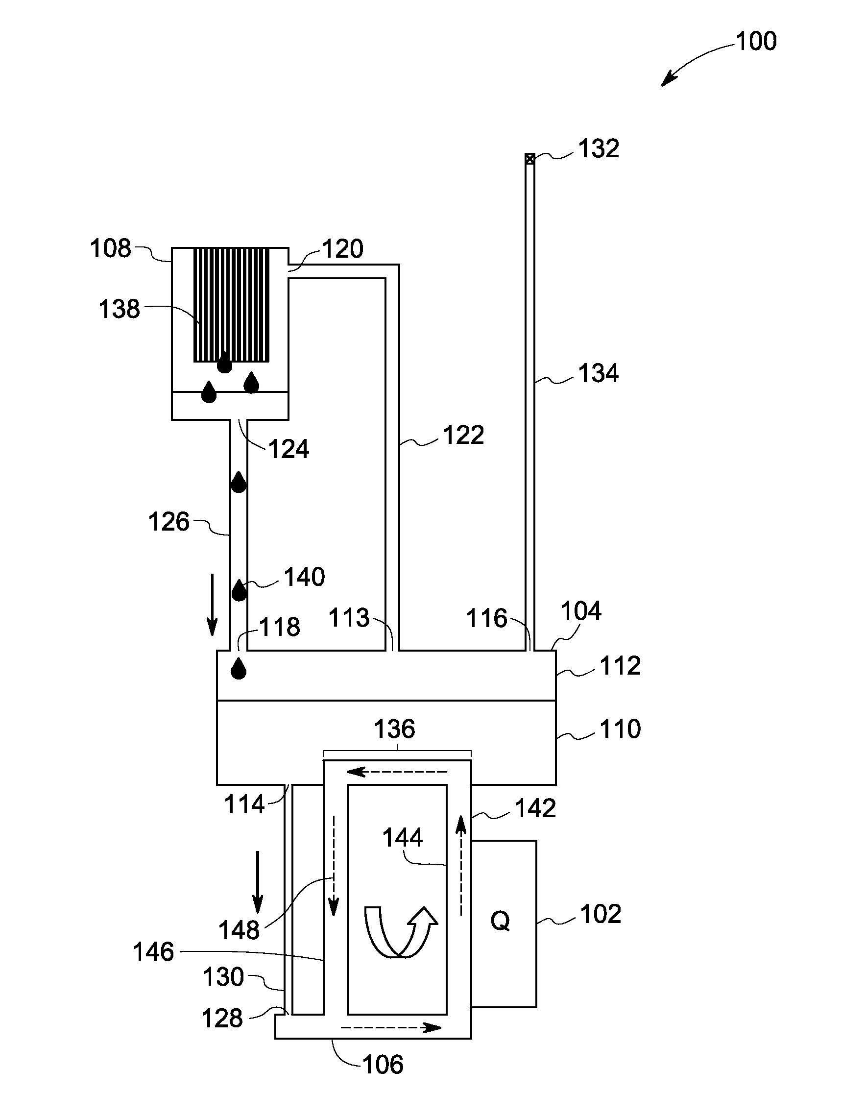
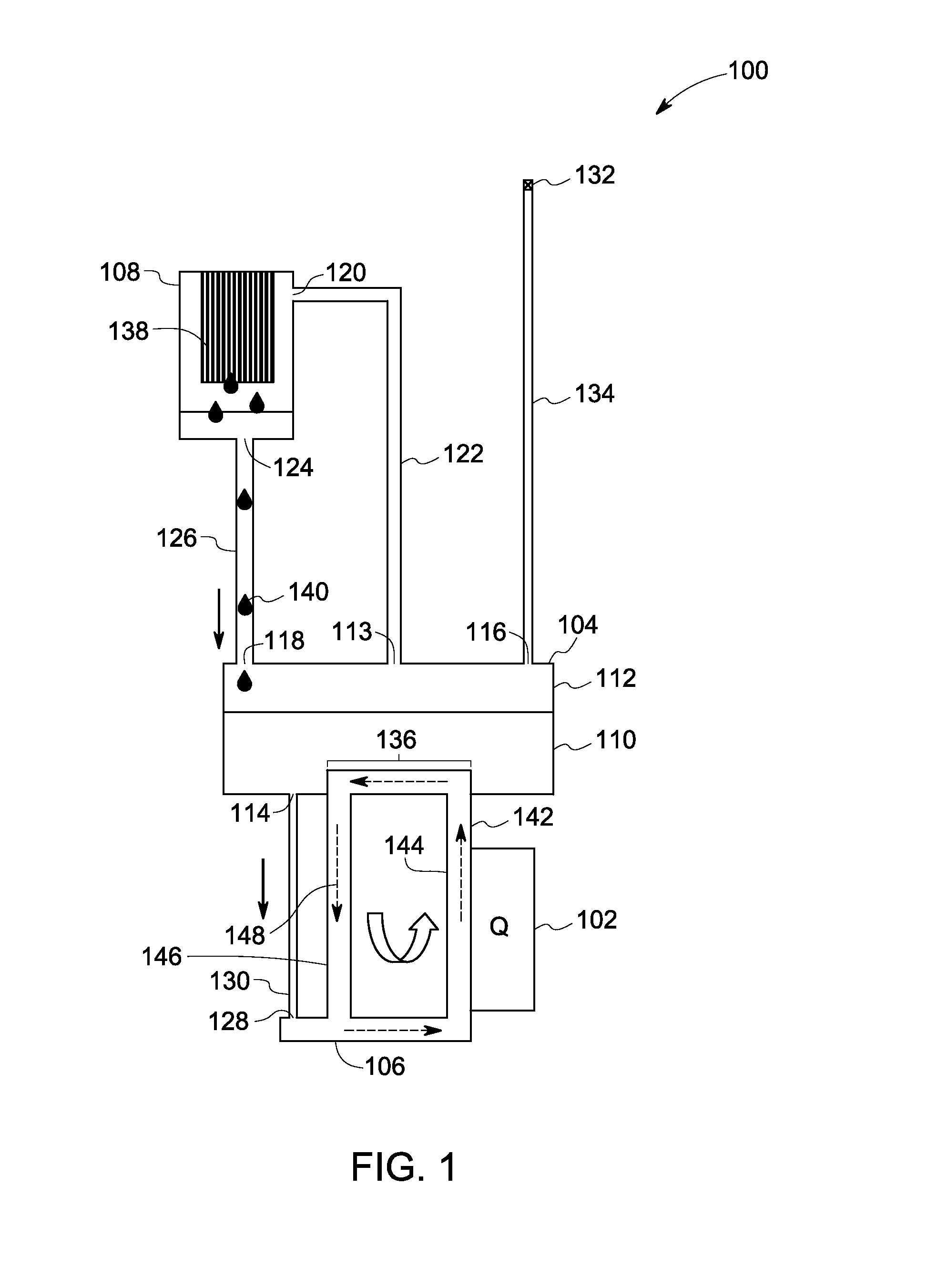
[0019]Turning now to the drawings, and referring to FIG. 1, a cross-sectional view of a thermosiphon cooling system 100, in accordance with aspects of the present technique, is depicted. The thermosiphon cooling system 100 may be configured to maintain a temperature of a superconducting unit 102 at or below a cryogenic temperature. The superconducting unit 102 may include superconducting magnets and / or coils, a gradient system, and their supporting structure held within the MRI s...


PUM


Abstract

A thermosiphon cooling system is presented. One embodiment of the thermosiphon cooling system includes a reservoir having a first portion configured to store a liquid coolant. The thermosiphon cooling system also includes a tubing unit coupled to the reservoir and disposed adjacent to at least one superconducting unit to be cooled and configured to receive the liquid coolant from the first portion of the reservoir, and circulate the received liquid coolant within the tubing unit to dissipate heat generated by the at least one superconducting unit. The received liquid coolant is circulated within the tubing unit by varying a density of the received liquid coolant at different portions of the tubing unit.

Description

BACKGROUND[0001]The disclosure relates generally to magnetic resonance imaging (MRI) systems and more specifically to a thermosiphon cooling system and method for cooling superconducting magnets in MRI systems.[0002]A superconducting magnet is used to produce a magnetic field in MRI systems. In some methods, an electric current from a power source is constantly applied to the superconducting magnet to produce the magnetic field. However, production of such a strong magnetic field entails a constant supply of the electric current in a range of hundreds of amperes. This constant supply of electric current to the superconducting magnet increases the running cost of the MRI system.[0003]Furthermore, in certain other techniques, the superconducting magnet may be subjected to different heat loads in the MRI system. It is desirable to transfer these heat loads away from the superconducting unit to maintain the superconducting magnet at a cryogenic temperature and to operate the superconduc...

Claims


Application Information

Patent Timeline
IPC IPC(8): F28D15/02
CPCG01R33/3804G01R33/3815F28D15/00H01F6/04H01L2924/0002F28D15/0266H01L2924/00F25B2400/17H01L23/427
Inventor STAUTNER, ERNST WOLFGANG
Owner GENERAL ELECTRIC CO
Learn More