Circuit Assembly and Method for Operating at Least one LED

a technology of circuit assembly and led, which is applied in the direction of electroluminescent light source, electric lighting source, and use of semiconductor-type lamps, etc., can solve the problem that the color of the light emitted by at least one led also changes when the dimming angle is changed

Inactive Publication Date: 2013-06-27
OSRAM GMBH
View PDF3 Cites 45 Cited by
  • Summary
  • Abstract
  • Description
  • Claims
  • Application Information

AI Technical Summary

Benefits of technology

The present invention relates to a circuit assembly for controlling the brightness of LED lights. The circuit assembly includes a control device that generates a pulse-width modulated (PWM) signal to dim the LEDs. The dimming angle is reflected in the pulse width, and a constant light color can be achieved over a wide dimming range without complex and costly A / D conversion. The control device ensures that the output power matches the dimming angle on the primary side. The circuit assembly also includes a filtering device that prevents sudden changes in brightness caused by the extinguishing of a triac. The invention provides a reliable and cost-effective solution for controlling the brightness of LED lights.

Problems solved by technology

What, though, is disadvantageous about that method is that the color of the light emitted by the at least one LED also changes when the dimming angle is changed.

Method used


Image

  • Circuit Assembly and Method for Operating at Least one LED
  • Circuit Assembly and Method for Operating at Least one LED
  • Circuit Assembly and Method for Operating at Least one LED

Examples


Embodiment Construction

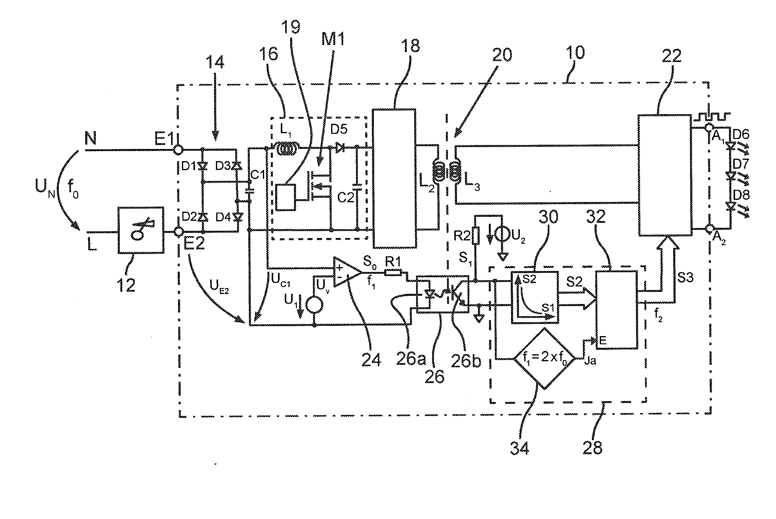
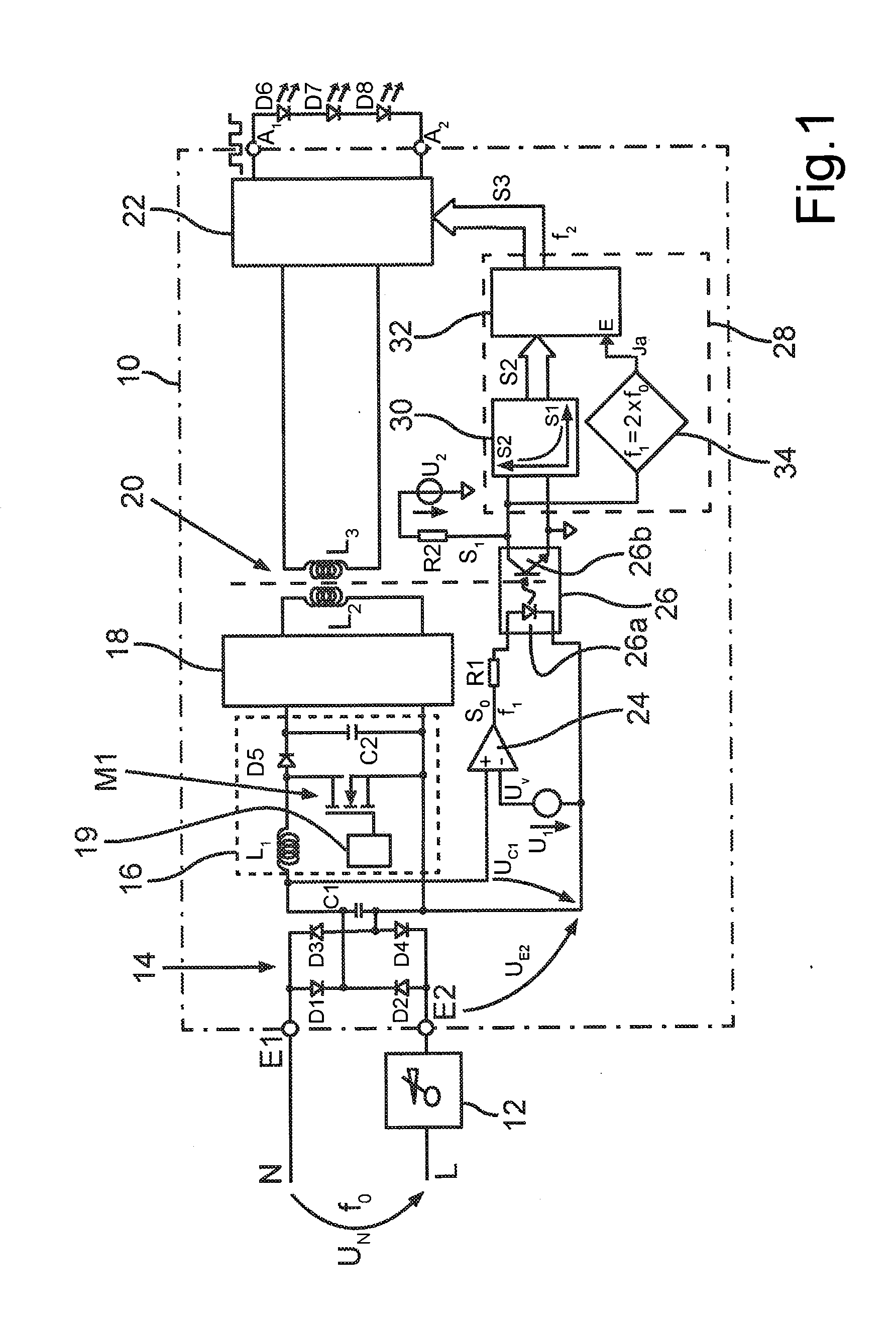
[0005]The object of the present invention is therefore to further develop a circuit assembly as cited in the introduction or, as the case may be, a method as cited in the introduction in such a way as to enable the at least one LED to be dimmed by means of a phase dimmer without changing the color of the light emitted by the at least one LED.

[0006]Said object is achieved by means of a circuit assembly having the features of claim 1 and by means of a method having the features of claim 11.

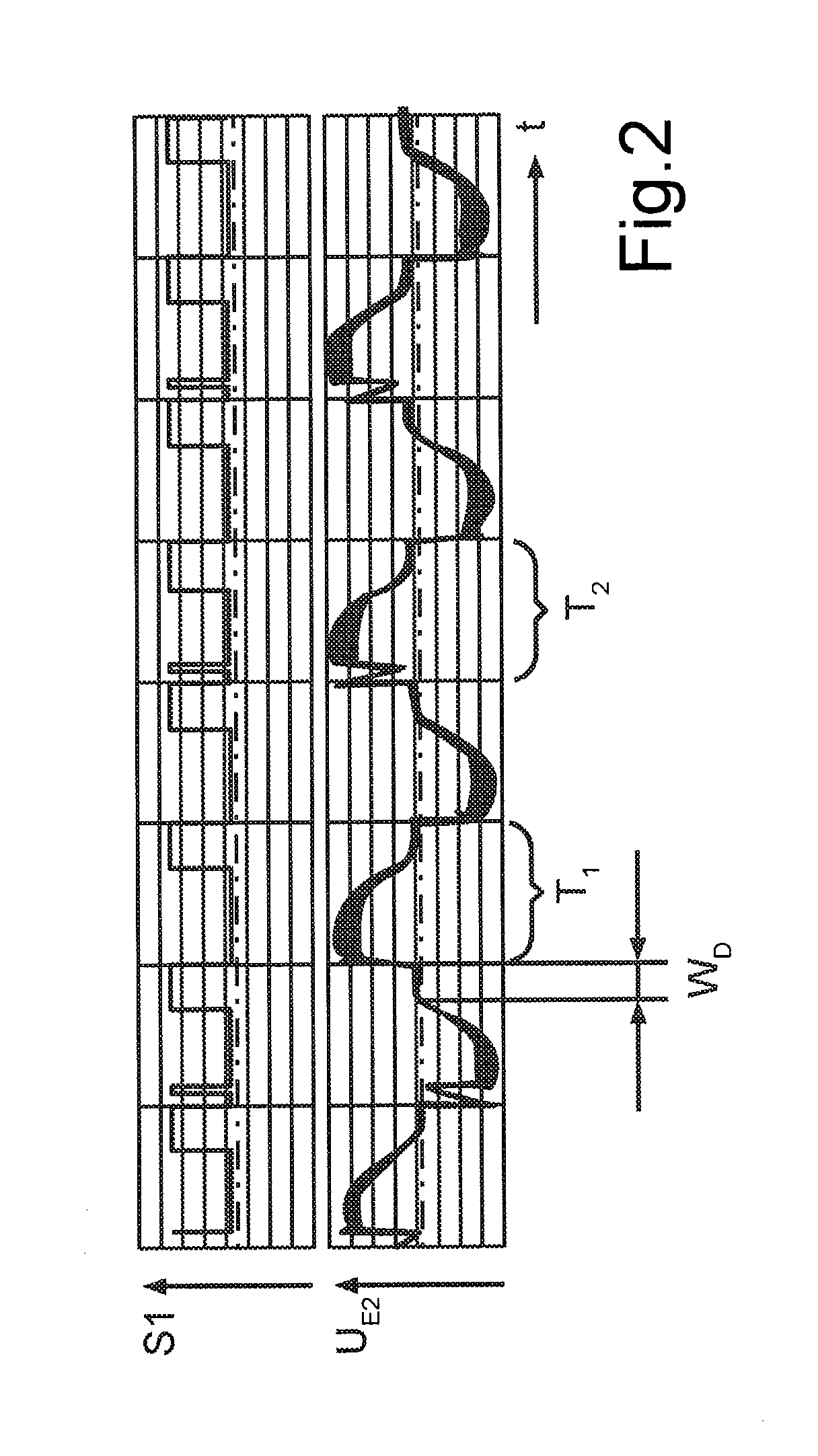
[0007]The present invention is based on the knowledge that the above will basically be made possible if the at least one LED is controlled by means of a PWM signal in the case of which the pulse width corresponds to the dimming angle by means of which the alternating supply voltage was modified by the phase dimmer. Because the amplitude of the PWM signal is constant independently of the dimming angle, the color of the light emitted by the at least one LED will—in contrast to the prior art—not change...


PUM


Abstract

Operating at least one LED on a circuit assembly having an input with first (E1) and second input terminals for coupling to an alternating supply voltage modified by a phase dimmer (12) for setting a dimming angle. Rectifier (14) has an input and an output, with its input being coupled to the circuit assembly's input. Signal (UC1) at the rectifier output is compared with a comparison value. PWM signal (S0) has a first frequency and the dimming angle is correlated with its pulse width. PWM signal having the first frequency (f1) is converted into a PWM signal (S3) that has a second frequency, and the dimming angle is correlated with its pulse width. Controllable current source (22), which is coupled on the input side to the rectifier output, is controlled with PWM signal (S3), with the at least one LED being coupled to the output of the controllable current source.

Description

TECHNICAL FIELD[0001]The present invention relates to a circuit assembly for operating at least one LED, said assembly having an input that has a first and second input terminal for coupling to an alternating supply voltage modified by a phase dimmer for setting a dimming angle, and having a rectifier that has an input and an output, with the rectifier's input being coupled to the circuit assembly's input. It relates further to a corresponding method for operating at least one LED. The terms “dimming angle” and “phase angle” are employed synonymously in the explanations that follow.PRIOR ART[0002]The present invention relates to a subject matter known by the term “retrofitting”. The aim therein is to replace incandescent or halogen lamps with lamps or luminaires having LEDs. The reason is that LEDs are more efficient and have a longer service life. What is of particular interest in this connection is for the aforementioned replacement of incandescent or halogen lamps with LEDs to be...

Claims


Application Information

Patent Timeline
IPC IPC(8): H05B37/02H05B44/00
CPCH05B33/0815H05B37/02Y02B20/347Y02B20/30H05B45/38H05B45/382H05B45/39
Inventor POLLISCHANSKY, THOMAS
Owner OSRAM GMBH
Why Eureka
Try Eureka