MIMO coverage over bi-directional leaky cables

a leaky cable and cam technology, applied in the field of indoor wireless communication systems, can solve the problems of complex installation, high bit-rate and spectral efficiency communication from base stations outside the physical structure, and traffic load in wireless communication

Active Publication Date: 2013-06-27
TELEFON AB LM ERICSSON (PUBL)
View PDF6 Cites 23 Cited by
  • Summary
  • Abstract
  • Description
  • Claims
  • Application Information

AI Technical Summary

Benefits of technology

[0005]With the above description in mind, then, an aspect of the present invention is to provide a wireless communications system comprising a node (such as a radio base station) and at least one leaky cable which seeks to mitigate, alleviate, or eliminate one or more of the above-identified deficiencies in the art and disadvantages singly or in any combination.

Problems solved by technology

A large part of today's traffic load in wireless communication comes from users inside physical structures such as office buildings, shopping malls, cafés and restaurants, etc.
Providing indoor users with good coverage, high bit-rate and spectrally efficient communication from base stations outside the physical structure is very challenging due to, for example, the penetration loss that occurs when the communication signals propagates through the walls of the building.
However, leaky cables are relatively expensive and complicated to install due to their weight and stiffness, and in multiple-stream applications such as in MIMO communications several cables need to be installed more or less in parallel which complicates the installation and makes them even more expensive to use.
Since a leaky cable leaks energy along its entire length, and since installations often requires quite long leaky cables, the signal-to-noise ratio (SNR) experienced by a user device located close to the end of the leaky cable is much less than if it was located at the beginning of the cable.
This leads to a very skew capacity distribution along the leaky cable which is undesired.
However, these amplifiers are not only expensive but also need power sources at each installation point which both complicates and increases the cost for the installation even more.

Method used


Image

  • MIMO coverage over bi-directional leaky cables
  • MIMO coverage over bi-directional leaky cables
  • MIMO coverage over bi-directional leaky cables

Examples


Embodiment Construction

[0032]Embodiments of the present invention will be described more fully hereinafter with reference to the accompanying drawings, in which embodiments of the invention are shown. This invention may, however, be embodied in many different forms and should not be construed as limited to the embodiments set forth herein. Rather, these embodiments are provided so that this disclosure will be thorough and complete, and will fully convey the scope of the invention to those skilled in the art. Like reference signs refer to like elements throughout the description.

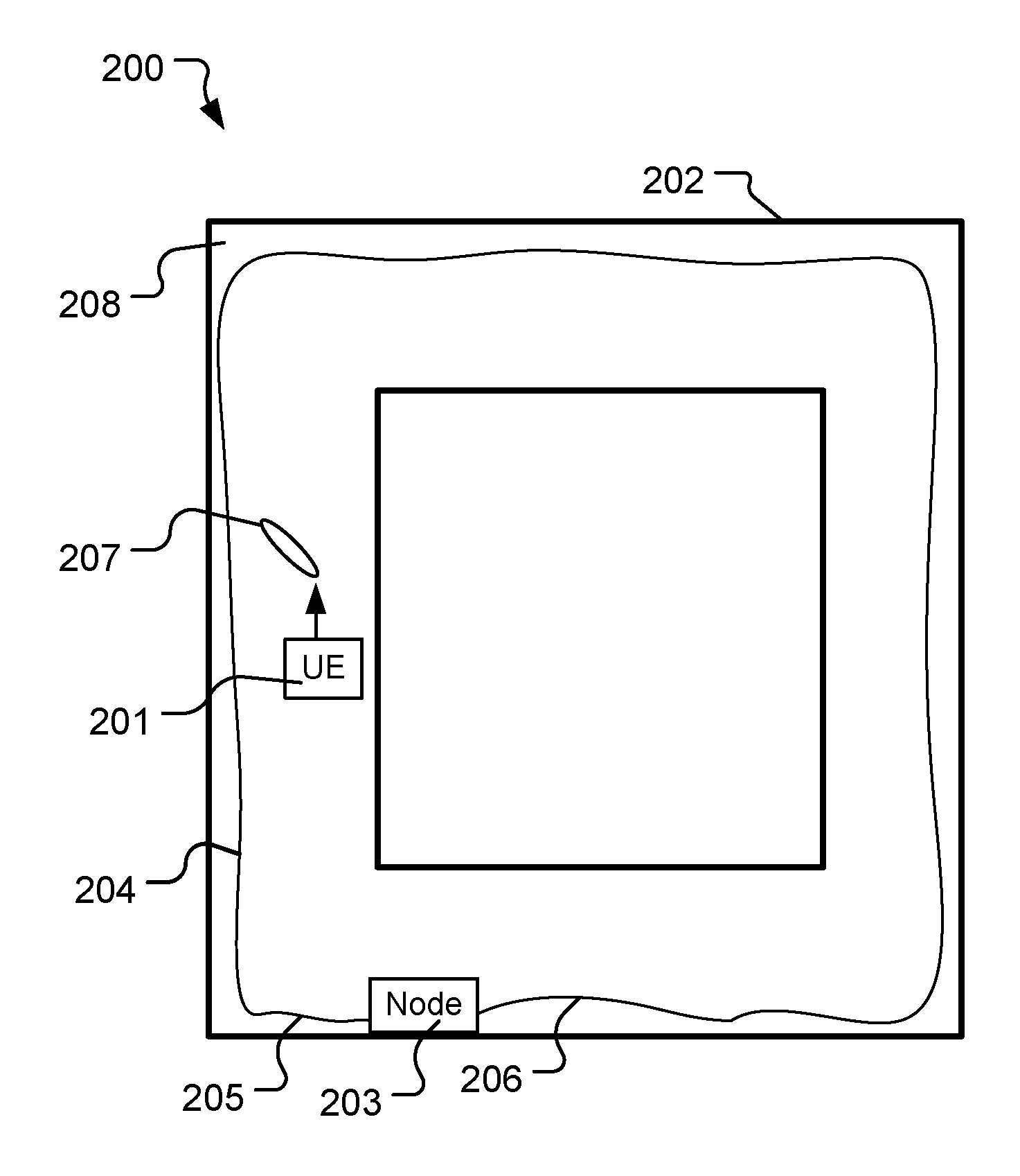
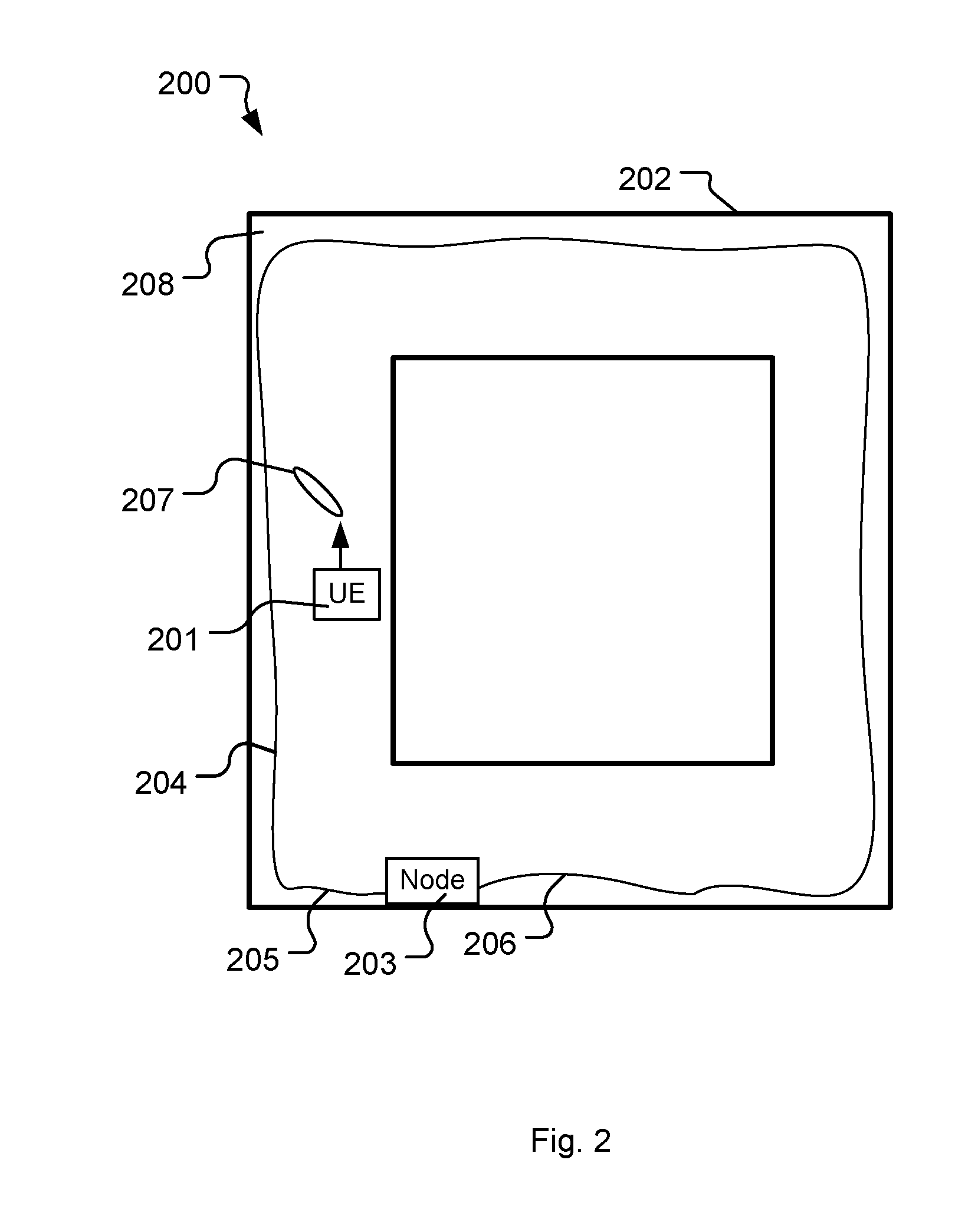
[0033]One way of offering good indoor coverage along with spectrally efficient communication and high bit-rate is to utilize an indoor wireless multiple-input multiple-output (MIMO) communications system comprising a node (i.e. radio base station) and a distributed antenna system (DAS).

[0034]A DAS is typically a network of spatially separated antenna nodes connected to a common source such as a radio base station, a node or a repea...


PUM


Abstract

The invention relates to a wireless communications system for communicating with user equipment located inside a physical structure. The system comprise a node having at least two antenna ports and being adapted for wireless communication with the user equipment, and at least one leaky cable having two ends wherein each end of the at least one leaky cable is connected to one of the antenna ports of the node. The at least one leaky cable is provided at least partially inside the physical structure and being adapted for wireless communication over a radio channel with the user equipment.

Description

TECHNICAL FIELD[0001]The present invention relates to the field of indoor wireless communication systems and, in particularly, to indoor multiple-input multiple-output (MIMO) communication systems using leaky cables for communicating with user equipment located inside a physical structure such as a building.BACKGROUND[0002]A large part of today's traffic load in wireless communication comes from users inside physical structures such as office buildings, shopping malls, cafés and restaurants, etc. Providing indoor users with good coverage, high bit-rate and spectrally efficient communication from base stations outside the physical structure is very challenging due to, for example, the penetration loss that occurs when the communication signals propagates through the walls of the building.[0003]A well-known way of enhancing the indoor coverage is to deploy a wireless communication system intended for indoor usage comprising an indoor radio base station (RBS) connected to a distributed...

Claims


Application Information

Patent Timeline
Patent Type & Authority Applications(United States)
IPC IPC(8): H01Q1/00
CPCH01Q1/007H04B5/0018H01Q13/203H04B7/0413
Inventor COLDREY, MIKAELASPLUND, HENRIKJOHANSSON, MARTINNILSSON, ANDREAS
Owner TELEFON AB LM ERICSSON (PUBL)
Why Eureka
Try Eureka