
Optical film, multilayer film, and manufacturing method thereof

a technology of optical film and multilayer film, applied in the field of optical film, to achieve the effect of reducing retardation layers that satisfy nz>nxny, stably manufacturing optical films, and displacing unevenness

Inactive Publication Date: 2013-06-27
FUJIFILM CORP
View PDF2 Cites 14 Cited by
  • Summary
  • Abstract
  • Description
  • Claims
  • Application Information

AI Technical Summary

Benefits of technology

The present invention aims to address the problem of display unevenness in liquid crystal display devices caused by changes in temperature and humidity. To achieve this, the invention provides an optical film with retardation layers that can meet specific conditions to reduce display unevenness. Additionally, the invention offers a multilayer film for manufacturing the optical film and a method for stable production of the film.

Problems solved by technology

However, if the multilayer structure including retardation layers showing the above predetermined optical characteristics is used for compensating a viewing angle of a liquid crystal display device, sometimes display unevenness is caused by change in usage environment such as temperature or humidity, so improvement is required regarding this point.

Method used


Image

  • Optical film, multilayer film, and manufacturing method thereof
  • Optical film, multilayer film, and manufacturing method thereof
  • Optical film, multilayer film, and manufacturing method thereof

Examples


examples

[0213]Hereinafter, the characteristics of the present invention will be described in more detail based on examples.

[0214]The materials, amount used, proportion, details of treatment, treatment procedure, and the like shown in the following examples can be appropriately changed as long as these do not depart from the object of the present invention. Accordingly, the scope of the present invention is not limited to the specific examples shown below.

[0215]In addition, a “part” is based on mass unless otherwise specified.

[0216][Measurement Method]

[0217]

[0218]A three-dimensional refractive index was measured by ellipsometry (model M2000V manufactured by J. A. Woollam Co., Inc.) at a wavelength of 550 nm.

[0219]1. Manufacture and Evaluation of Optical Film and Multilayer Film

[0220](1) Preparation of Dope

[0221]

[0222]Dopes A were respectively prepared using the respective polymer materials described in the following tables. As a solvent, ethylene chloride was used. However, in some examples,...


PUM


Abstract

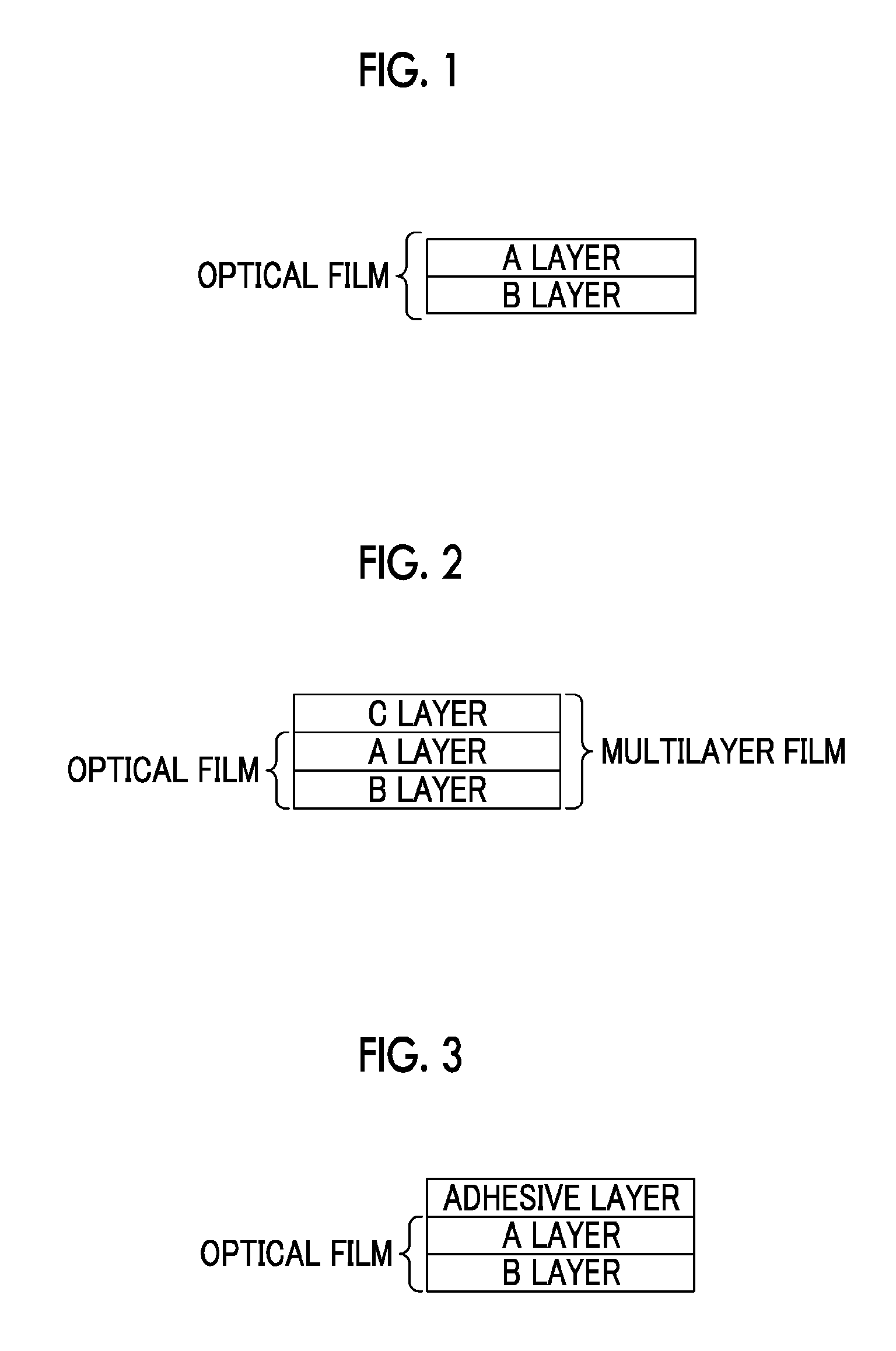
An optical film that does not cause display unevenness, includes a retardation layer A (A layer) satisfying the following relational expression, nz>nx≧ny here, nx represents an in-plane refractive index in a direction of an in-plane slow axis, ny represents an in-plane refractive index in a direction orthogonal to the direction of an in-plane slow axis, and nz represents a refractive index in a thickness direction; and a retardation layer B (B layer) of which in-plane retardation Re and thickness direction retardation Rth satisfy the following relational expressions: 0 nm≦Re≦20 nm and 50 nm≦Rth≦300 nm, wherein the total film thickness is 5 μm to 40 μm.

Description

BACKGROUND OF THE INVENTION[0001]1. Field of the Invention[0002]The present invention relates to an optical film that is useful as a retardation film or the like used for a liquid crystal display device, a multilayer film that is used for manufacturing the optical film, and a method that can stably manufacture these films.[0003]2. Description of the Related Art[0004]In the related art, retardation films called, for example, a positive C-plate and a positive B-plate that satisfy nz>nx≧ny when an in-plane refractive index in the direction of an in-plane slow axis is nx, an in-plane refractive index in a direction orthogonal to the direction of an in-plane slow axis is ny, and a refractive index in a thickness direction is nz have been used as a viewing angle compensation film or the like of a liquid crystal display device. The retardation film satisfying the above characteristics is generally used in a liquid crystal display device, as a multilayer structure including retardation l...

Claims


Application Information

Patent Timeline
IPC IPC(8): G02B5/30
CPCG02B5/3083G02B5/3016G02B5/305G02F1/133528
Inventor TAMADA, TAKASHITAKEDA, JUN
Owner FUJIFILM CORP
Learn More