
Adjustable output solid-state lighting device

a lighting device and output technology, applied in the direction of fixed installation, lighting and heating equipment, coupling device connection, etc., can solve the problem that the dimmer does not enable individualized intensity adjustment for each ligh

Active Publication Date: 2013-06-27
EXPRESS IMAGING SYST
View PDF46 Cites 75 Cited by
  • Summary
  • Abstract
  • Description
  • Claims
  • Application Information

AI Technical Summary

Benefits of technology

The present patent provides lighting devices that can adjust the brightness of individual areas without affecting other areas. This feature allows for customization and flexibility in lighting options.

Problems solved by technology

Thus, where there are two or more lights on a single circuit, the dimmer does not enable individualized intensity adjustment to each of the lights.
Such light sources have the same restriction as other types of light sources in that all of the light sources on the power line are dimmed to the same level, which is not desirable in many locations.

Method used


Image

  • Adjustable output solid-state lighting device
  • Adjustable output solid-state lighting device
  • Adjustable output solid-state lighting device

Examples


Embodiment Construction

[0034]In the following description, certain specific details are set forth in order to provide a thorough understanding of various disclosed embodiments. However, one skilled in the relevant art will recognize that embodiments may be practiced without one or more of these specific details, or with other methods, components, materials, etc. In other instances, well-known structures associated with lighting systems, for example power converters, thermal management structures and subsystems, and / or solid state lights have not been shown or described in detail to avoid unnecessarily obscuring descriptions of the embodiments.

[0035]Unless the context requires otherwise, throughout the specification and claims which follow, the word “comprise” and variations thereof, such as, “comprises” and “comprising” are to be construed in an open, inclusive sense, that is as “including, but not limited to.”

[0036]Reference throughout this specification to “one embodiment” or “an embodiment” means that ...


PUM

PropertyMeasurementUnit
Poweraaaaaaaaaa
Electrical resistanceaaaaaaaaaa
Currentaaaaaaaaaa

Abstract

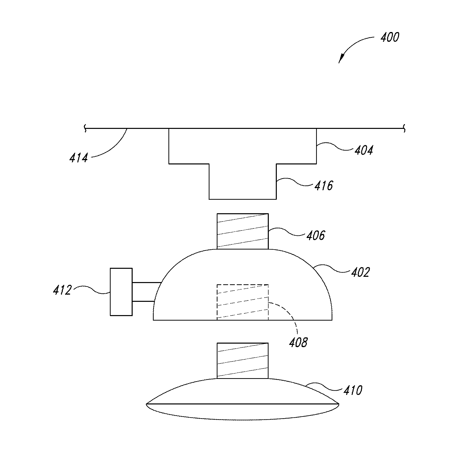
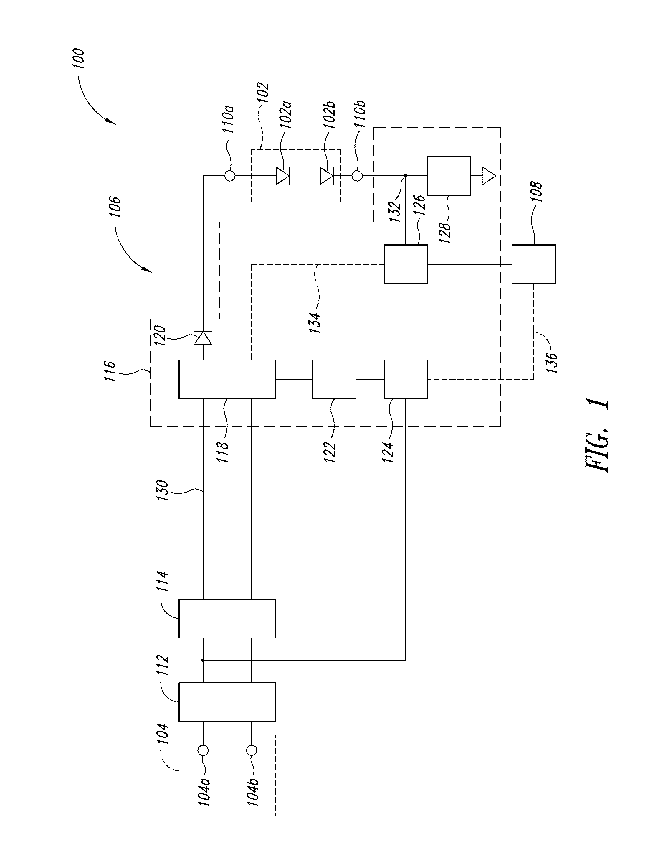
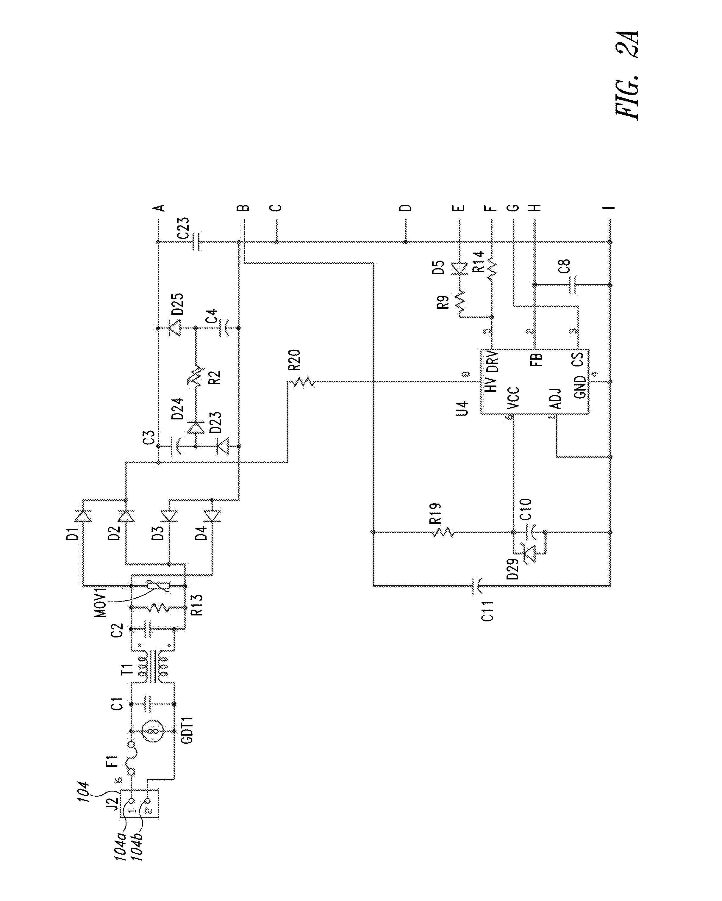
A solid-state lighting device has user-engageable actuator physically manipulable by a user and accessible from an exterior of the device to adjust an amount of light output. The user-engageable actuator may take the form of a knob, slider, lever, or other manipulable surface or structure. The user-engageable actuator may extend partially or fully from a housing, or alternatively be recessed or otherwise within the housing with access provided via an aperture, slot or opening. Access may be directly by the user (e.g., finger) or via a tool (e.g., screw driver, Allen wrench, socket) manipulated by the user. The actuator may form part of an adjustment component (e.g., potentiometer, rheostat) which supplies an adjustable output to a drive circuit or electronics. The adjustment component may be electrically coupled to either a primary or secondary side of a transformer, which forms part of a power converter (e.g., flyback).

Description

BACKGROUND[0001]1. Technical Field[0002]This disclosure is generally related to solid-state lighting devices having an adjustable output intensity.[0003]2. Description of the Related Art[0004]Traditional lighting systems adjust an output intensity of light by increasing or decreasing a line voltage, or by chopping the line voltage at some phase angle, either “phase cut” or “reverse phase cut”. Phase cut dimmers typically use a semiconductor device which is switched off at the zero crossing of the AC line voltage, and switched on at some phase angle later in the cycle to effectively modulate the power into the lighting device. For example, a typical low-cost household dimmer uses a TRIAC or SCR device to switch the AC power off during the line cycle. Reverse phase cut dimmers use more complex circuitry to turn on the semiconductor device at the zero crossing of the AC line, and turn off at some phase angle later in the cycle. Reverse phase dimmers have the advantage of lower electric...

Claims


Application Information

Patent Timeline
IPC IPC(8): F21V23/04H05K13/00H05B44/00
CPCH05B33/0803H05B33/0851F21V23/04H05K13/0023F21K9/13Y10T29/49117H01R33/9453F21Y2101/02Y02B20/383H05B33/0815F21V29/74F21S8/026F21K9/23F21Y2115/10H05B45/10H05B45/382Y02B20/30H05B45/36H05B45/385H05B45/325H05K13/00
Inventor REED, WILLIAM G.
Owner EXPRESS IMAGING SYST
Learn More