Amplifier and amplifying method

a technology of amplifier and amplifier, applied in the field of amplifier, can solve the problems of wasting operating power, power consumption, unsatisfactory reactive power, etc., and achieve the effect of reducing power consumption

Inactive Publication Date: 2013-06-27
HARMAN INT JAPAN +1
View PDF2 Cites 105 Cited by
  • Summary
  • Abstract
  • Description
  • Claims
  • Application Information

AI Technical Summary

Benefits of technology

[0016]The amplifier and amplifying method described above are able to reduce power consumption.

Problems solved by technology

This reactive power is not desirable from the viewpoint of low power consumption.
In this case, although it is sufficient to turn on only the channel nearest the driver (such as the right-front) for the driver to be able to hear, the power to all of the channels ends up being turned on, which ends up wasting operating power.
Also, with a D-class amplifier, a high carrier frequency is undesirable in order to obtain high-quality audio characteristics.
Modulating a carrier frequency higher for sound that does not need to be high-quality is not desirable from the viewpoint of low power consumption.
An increase in switching loss results in a decrease in switching efficiency, which leads to an increase in power consumption.

Method used


Image

  • Amplifier and amplifying method
  • Amplifier and amplifying method
  • Amplifier and amplifying method

Examples


example embodiments

[0024]

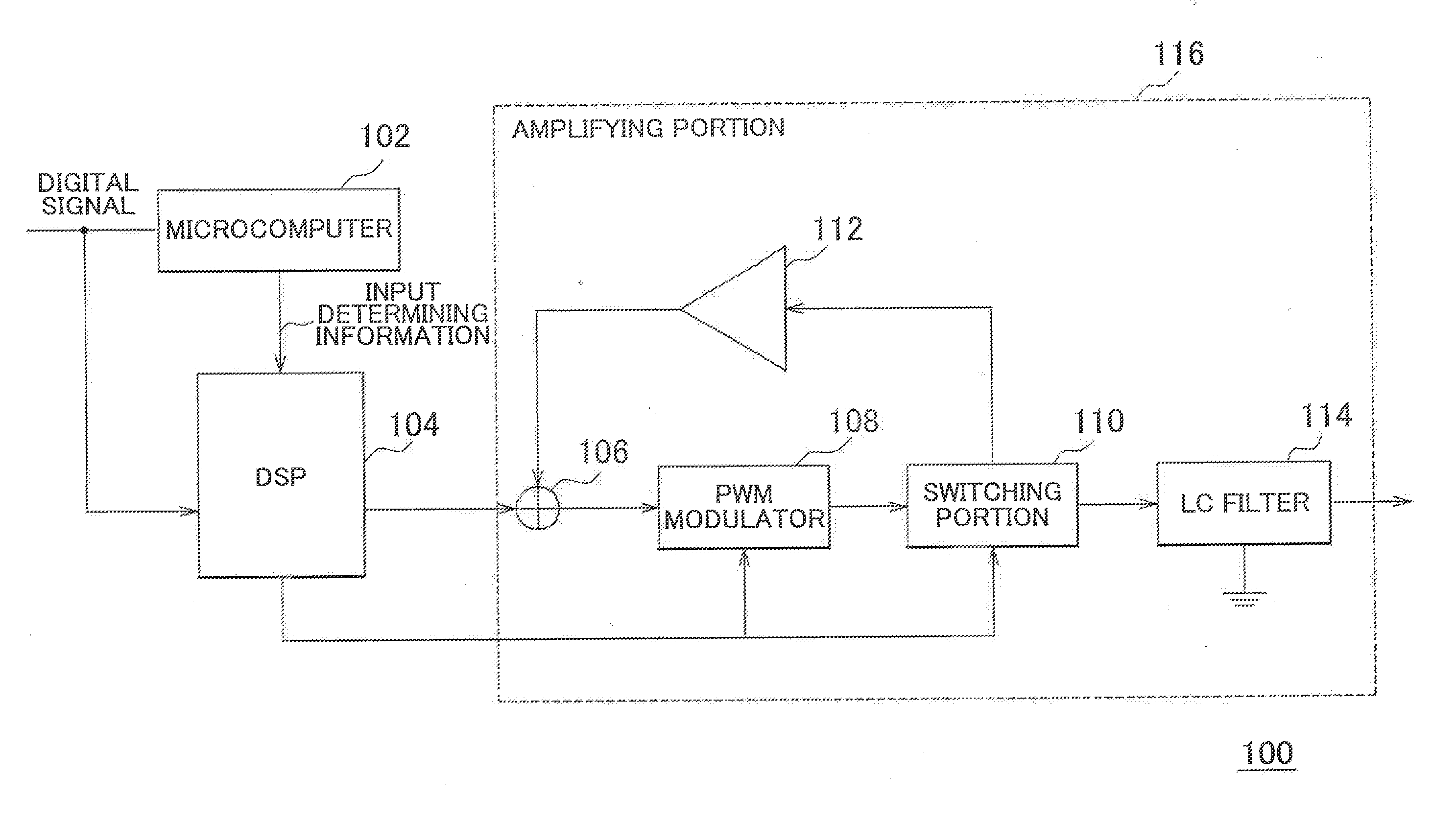
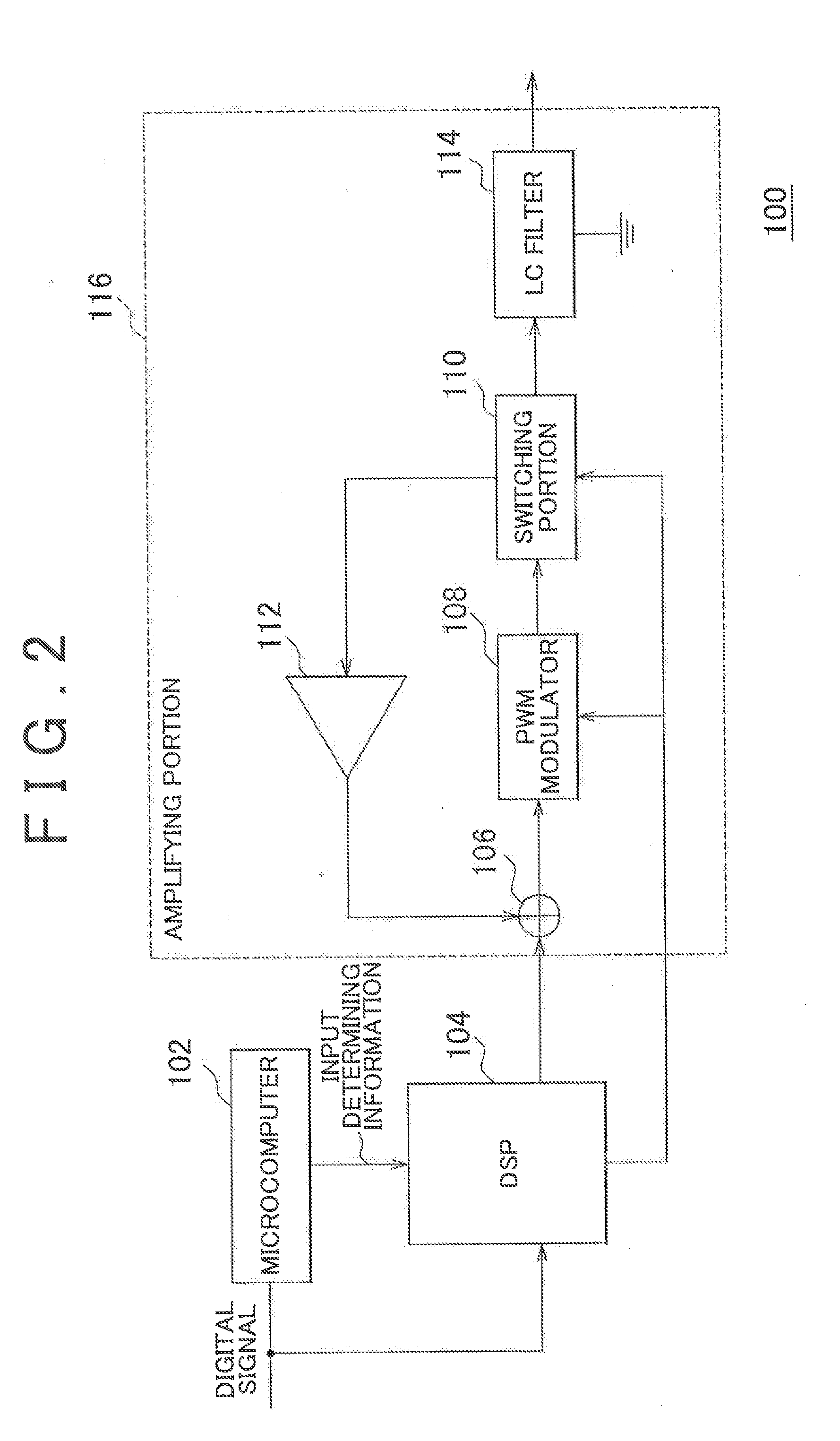
[0025]An amplifier 100 is provided in a device. This device includes on-board devices and audio devices and the like. The audio devices may include portable audio devices and devices capable of playing CDs and radio or the like. The audio devices may also include devices capable of playing data compressed according to a predetermined compression sound file format. This format may include MP3.

[0026]In this example embodiment, a case in which the amplifier 100 is provided in an on-board device will be described as an example. This on-board device is able to output various sound and / or voice (hereinafter simply referred to as “sound”). For example, the sound source of sound output from the on-board device may be a DVD (Digital Versatile Disk), a CD or AM radio. Sound from DVDs and CDs must be high quality, while sound from AM radio does not need to be as high quality as sound from DVDs and CDs. Sound that has been converted to a digital signal may also be input to the amplifier 1...


PUM


Abstract

An amplifier that modulates a carrier frequency according to a digital signal and amplifies the modulated signal includes a determining portion that determines at least one of a sound quality required for the digital signal, a sound source of the digital signal, and a type of sound of the digital signal, a carrier frequency setting portion that sets a carrier frequency according to a result of the determination, and a pulse-width modulating portion that pulse-width modulates the carrier frequency according to the digital signal.

Description

BACKGROUND OF THE INVENTION[0001]1. Field of the invention[0002]The invention relates to an amplifier, and more particularly, a D-class amplifier.[0003]2. Description of Related Art[0004]FIG. 1 is a view of a D-class amplifier.[0005]This D-class amplifier includes a gate driver, a transistor Tr1, a transistor Tr2, and a LC filter.[0006]According to the D-class amplifier shown in FIG. 1, the gate driver operates while the power is on. Because the gate driver operates, a switching signal is generated on the output side even when there is no input signal. The duty ratio of this switching signal is 50%, for example. This switching signal is consumed as reactive power by the LC filter that is formed by L1 and C1.[0007]With a D-class amplifier, because the gate driver operates even when there is no input signal, a switching signal is generated on the output side, and this switching signal is consumed as reactive power. This reactive power is not desirable from the viewpoint of low power c...

Claims


Application Information

Patent Timeline
Patent Type & Authority Applications(United States)
IPC IPC(8): H03F3/68
CPCH03F3/68H03F3/217
Inventor MAENO, SEIGENTOMONAGA, HIROSHI
Owner HARMAN INT JAPAN
Why Eureka
Try Eureka