
Methods of forming graphene

a graphene and graphene technology, applied in the field of graphene formation, can solve the problems of the current bottleneck in the method of obtaining high-performance electricity and hydrogen storage materials, and the inability to form graphene of high yield by only electrolysis without other mechanical processes

Inactive Publication Date: 2013-06-27
IND TECH RES INST
View PDF2 Cites 22 Cited by
  • Summary
  • Abstract
  • Description
  • Claims
  • Application Information

AI Technical Summary

Benefits of technology

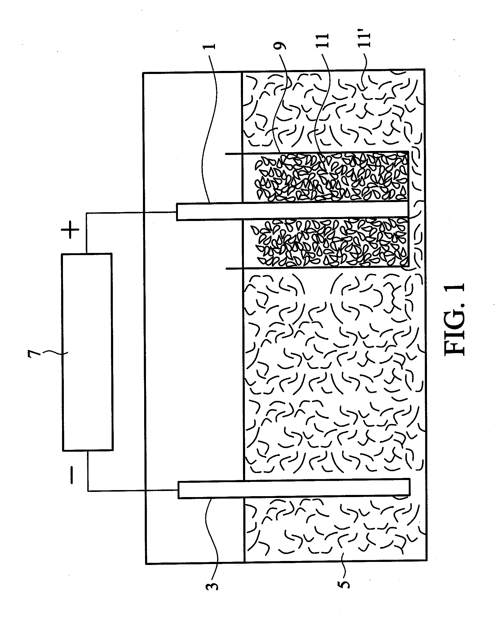
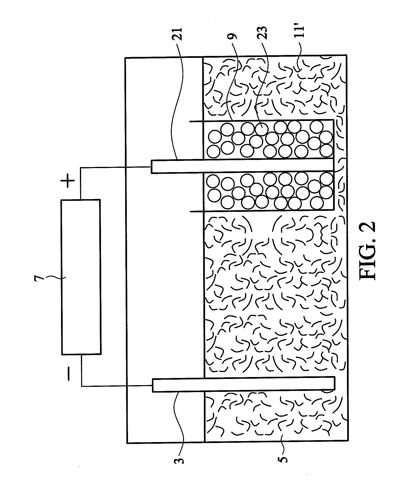
The patent text describes a method for making graphene by using a semipermeable membrane to separate a graphite electrode from a negative electrode in an acidic electrolyte. This method allows for the continuous production of a first graphene oxide with a larger size than the membrane pore size, which is then split into smaller second graphene oxide to penetrate through the membrane. The second graphene oxide is then collected and chemically reduced to obtain graphene. The technical effect of this method is the efficient production of high-quality graphene in a controlled environment.

Problems solved by technology

However, methods of obtaining electricity and hydrogen storage materials with high performance are currently at a bottleneck.
However, a graphene of high yield cannot be formed by only electrolysis without other mechanical processes.

Method used


Image

  • Methods of forming graphene
  • Methods of forming graphene
  • Methods of forming graphene

Examples


example 1

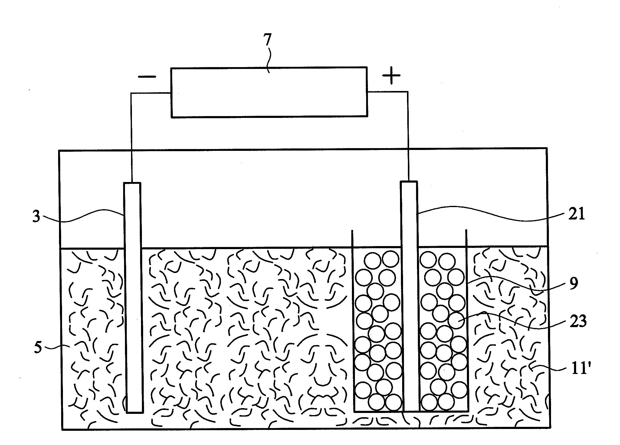
[0028]100 mL of a sulfuric acid solution (0.24M) was prepared as an acidic electrolyte having a pH value of about 0.7. A graphite plate (1.44 g and 20×20×2 mm, commercially available from Central Carbon Co., Ltd.) was wrapped in a semipermeable membrane (single-layered polypropylene with a pore size of 40 nm, commercially available from Celgard) and connected to a positive electrode of a direct current power supply. A platinum wire was connected to a negative electrode of the direct current power supply. Subsequently, the graphite plate wrapped in the semipermeable membrane and the platinum wire were dipped into the acidic electrolyte. A constant voltage of 2.5V was provided by the direct current power supply to process a pre-electrolysis for 1 minute, such that the graphite plate was completely impregnated with the electrolyte. Thereafter, electrolysis was performed at a voltage of 10V for 3 hours. During the electrolysis process, the graphite plate gradually exfoliated and the bla...

example 2

[0029]100 mL of a sulfuric acid solution (0.24M) was prepared as an acidic electrolyte having a pH value of about 0.7. Graphite particles (individual diameter of 3 μm, totally 2 g, commercially available from Central Carbon Co., Ltd.) and a platinum wire were wrapped in a semipermeable membrane (single-layered polypropylene with a pore size of 40 nm, commercially available from Celgard), and the platinum wire was connected to a positive electrode of a direct current power supply. Another platinum wire was connected to a negative electrode of the direct current power supply. Subsequently, the graphite particles and the platinum wire wrapped in the semipermeable membrane and the other platinum wire were dipped into the acidic electrolyte. A constant voltage of 2.5V was provided by the direct current power supply to process a pre-electrolysis for 1 minute, such that the graphite particles were completely impregnated with the electrolyte. Thereafter, electrolysis was performed at a volt...


PUM


Abstract

Disclosed is a method of forming graphene. A graphite positive electrode (or positive electrode together with graphite material) wrapped in a semipermeable membrane and a negative electrode are dipped in an acidic electrolyte to conduct an electrolysis process. As such, a first graphene oxide having a size larger than a pore size of the semipermeable membrane is exfoliated from the graphite positive electrode (or the graphite material). The electrolysis process is continuously conducted until a second graphene oxide is exfoliated from the first graphene oxide, wherein the second graphene oxide has a size which is smaller than the pore size of the semipermeable membrane to penetrate through the semipermeable membrane. The second graphene oxide diffused into the acidic electrolyte outside of the semipermeable membrane is collected. Finally, the collected second graphene oxide is chemically reduced to obtain a graphene.

Description

CROSS REFERENCE TO RELATED APPLICATIONS[0001]This Application claims priority of Taiwan Patent Application No. 100148809, filed on Dec. 27, 2011, the entirety of which is incorporated by reference herein.BACKGROUND OF THE INVENTION[0002]1. Field of the Invention[0003]The disclosure relates to a method of forming graphene, and in particular relates to electrolysis for forming the graphene.[0004]2. Description of the Related Art[0005]The topic of green energy grows in importance when fossil fuels begin to run out. Electricity and hydrogen storage research is a core research area of super capacitors and fuel cells. However, methods of obtaining electricity and hydrogen storage materials with high performance are currently at a bottleneck. A single atomic layer graphene having a theoretically specific capacity of 531 F / g, a theoretically hydrogen storage value of 6%, and a theoretically electrical conductivity of 10−6 Ω / cm may serve as an ideal electricity and hydrogen storage material....

Claims


Application Information

Patent Timeline
IPC IPC(8): C01B31/04B82Y40/00
CPCC25B1/00B82Y40/00B82Y30/00C01B31/0476C01B32/192
Inventor HSIEH, YU-TSEHUANG, KUN-PINGLIN, PANG
Owner IND TECH RES INST
Learn More