Process of producing ceramic matrix composites and ceramic matrix composites formed thereby

a ceramic matrix and composite technology, applied in the field of ceramic matrix composites and ceramic matrix composites formed thereby, can solve the problems of not being fully dense and porous, and achieve the effect of exceeding the melting point of elemental silicon

Inactive Publication Date: 2013-07-04
GENERAL ELECTRIC CO
View PDF11 Cites 86 Cited by
  • Summary
  • Abstract
  • Description
  • Claims
  • Application Information

AI Technical Summary

Benefits of technology

[0015]A technical effect of the invention is the ability to produce SiC-based CMC and CFCC articles that are capable of use at temperatures exceeding the melting point of elemental silicon and silicon alloys. While previous methods have sought to eliminate elemental silicon and low-melting silicon alloys from CMC articles to yield a matrix phase formed entirely of refractory silicon-based materials, such methods have yielded matrices that contain porosity and therefore are not fully dense. In contrast, the present invention is directed to producing CMC articles that are not only essentially free of elemental silicon and low-melting silicon alloys, but also contain a dense matrix that is essentially free of porosity, for example, contains less than 5 vol. % porosity.
[0016]Other aspects and advantages of this invention will be better appreciated from the following detailed description.

Problems solved by technology

While previous methods have sought to eliminate elemental silicon and low-melting silicon alloys from CMC articles to yield a matrix phase formed entirely of refractory silicon-based materials, such methods have yielded matrices that contain porosity and therefore are not fully dense.

Method used


Image

  • Process of producing ceramic matrix composites and ceramic matrix composites formed thereby
  • Process of producing ceramic matrix composites and ceramic matrix composites formed thereby
  • Process of producing ceramic matrix composites and ceramic matrix composites formed thereby

Examples


Embodiment Construction

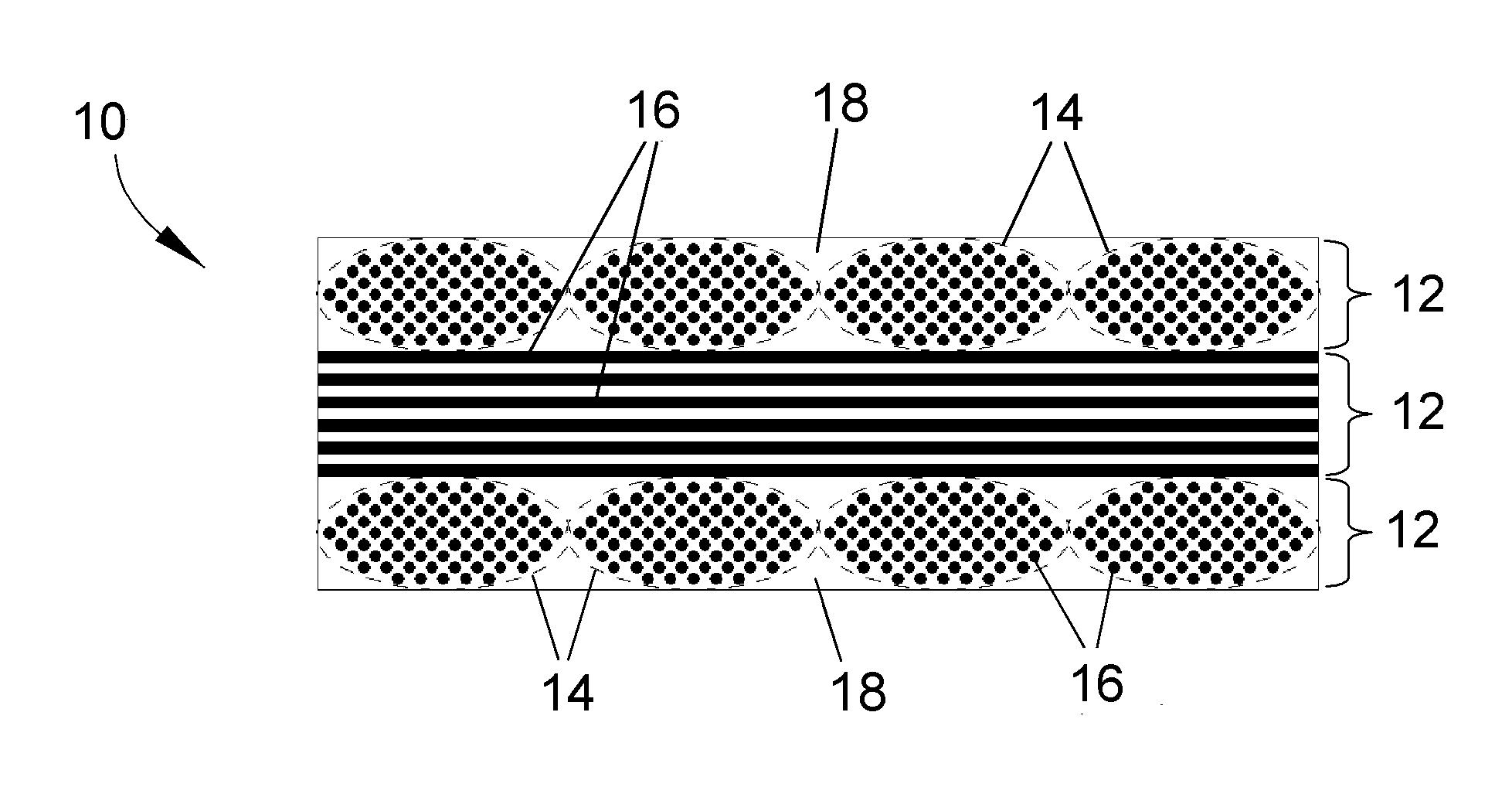
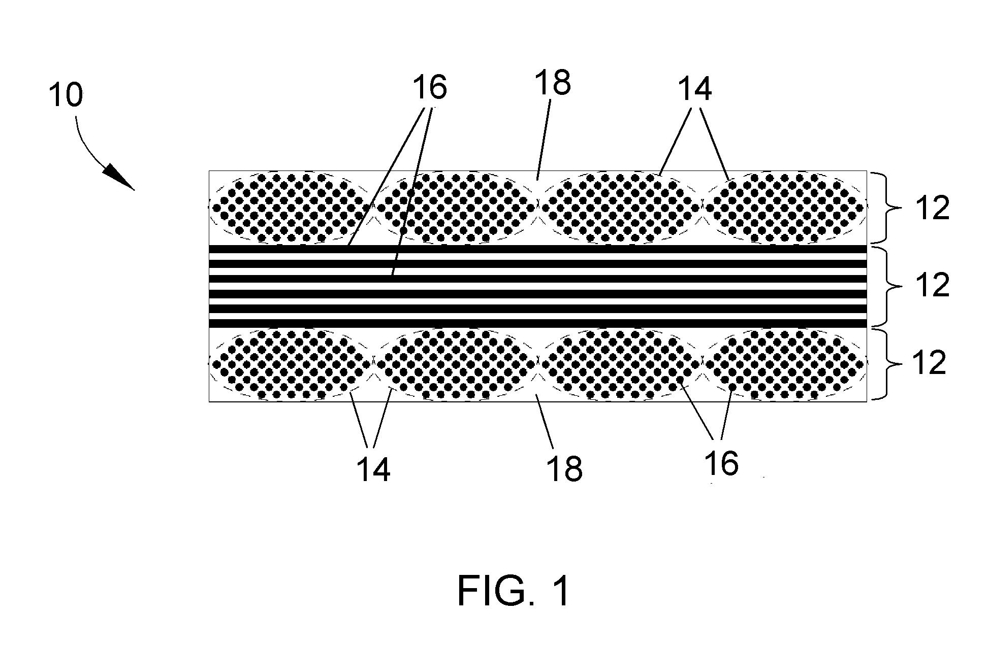
[0019]The present invention will be described in terms of processes for producing CMC articles, including CFCC articles, that can be used at temperatures exceeding the melting point of low-melting silicon alloys (for example, about 1357° C.), and preferably up to temperatures of at least 1480° C., and therefore well over the melting point of silicon and low-melting alloys thereof. CMC materials of particular interest to the invention are those containing silicon, such as CMC's containing silicon carbide as the reinforcement and / or matrix material, a particular example of which is continuous silicon carbide fibers in a matrix of silicon carbide. However, other silicon-containing materials are also within the scope of the invention, including ceramics such as silicon nitride and silicides (intermetallics) such as niobium silicide and molybdenum silicide. While various applications are foreseeable, particular applications for the component 10 include components of gas turbine engines, ...


PUM

PropertyMeasurementUnit
temperaturesaaaaaaaaaa
temperatureaaaaaaaaaa
melting pointaaaaaaaaaa

Abstract

A process for producing a silicon-containing CMC article. The process entails depositing one or more coating layers on silicon carbide (SiC) fibers, drawing the coated SiC fibers through a slurry to produce slurry-coated fiber material, and then processing the slurry-coated SiC fiber material to form unidirectional prepreg tapes. The tapes are stacked and then fired to yield a porous preform. The porous preform is then further densified by infiltrating the porosity therein to yield a CMC article. Infiltration can be achieved by a series of polymer infiltration and pyrolysis (PIP) steps, by melt infiltration (MI) after filling the porosity in the preform with carbon or one or more refractory metal, by chemical vapor infiltration (CVI), or by a combination of these infiltration techniques.

Description

CROSS REFERENCE TO RELATED APPLICATIONS[0001]This application claims the benefit of U.S. Provisional Application No. 61 / 581,129, filed Dec. 29, 2011, the contents of which are incorporated herein by reference.STATEMENT REGARDING FEDERALLY SPONSORED RESEARCH[0002]This invention was made with government support under Contract No. N00421-08-C-0041 awarded by the Navy. The Government has certain rights in the invention.BACKGROUND OF THE INVENTION[0003]The present invention generally relates to ceramic matrix composite (CMC) articles and processes for their production. More particularly, this invention is directed to a process of producing silicon-containing CMC articles that includes processing steps capable of yielding CMC articles that exhibit desirable physical, mechanical, and microstructural properties at elevated temperatures.[0004]Higher operating temperatures for gas turbine engines are continuously sought in order to increase their efficiency. Though significant advances in hig...

Claims


Application Information

Patent Timeline
Patent Type & Authority Applications(United States)
IPC IPC(8): C04B35/64F02C7/00B32B18/00
CPCC04B35/64Y10T29/49236F02C7/00F05D2300/2261C04B35/573C04B35/58092C04B35/591C04B35/6286C04B35/62863C04B35/62865C04B35/62868C04B35/62871C04B35/62894C04B35/806F01D25/00C04B2235/3418C04B2235/3826C04B2235/3839C04B2235/3856C04B2235/3873C04B2235/3886C04B2235/3891C04B2235/3895C04B2235/404C04B2235/424C04B2235/428C04B2235/48C04B2235/483C04B2235/5244C04B2235/5256C04B2235/5268C04B2235/614C04B2235/616C04B2235/72C04B2235/728C04B2235/77C04B2235/80C04B2237/365C04B2237/38F05D2300/6033C04B2235/658C04B2235/6581C04B2237/341C04B2237/368C04B2237/52C04B2237/525C04B2237/61H04W4/008H04W4/023B32B18/00C04B35/80H04W4/80Y10T428/249986
Inventor KIRBY, GLEN HAROLDSTEIBEL, JAMES DALEGOSS, NATHANIEL DAVID
Owner GENERAL ELECTRIC CO
Why Eureka
Try Eureka