Gear motor assembly

a gear motor and assembly technology, applied in the direction of gear lubrication/cooling, dynamo-electric machines, roofs, etc., can solve the problems of loud noise, achieve the effect of reducing friction, improving lubricity, and low gear vibration during operation

Inactive Publication Date: 2013-07-04
JOHNSON ELECTRIC SA
View PDF6 Cites 13 Cited by
  • Summary
  • Abstract
  • Description
  • Claims
  • Application Information

AI Technical Summary

Benefits of technology

[0012]In embodiments of the present invention, as the slot is especially formed to receive lubricant, compared to gear motor assemblies of the prior art, less room between the output shaft and the bearing is needed to retain the lubricant. Therefore, the gear motor assembly is able to reduce friction while maintaining low vibration of the gear during operation. From another aspect, due to the slot extending through the entire bearing, the whole inner surface of the bearing can contact the lubricant, which improves the lubricity.

Problems solved by technology

Thus, less lubricant can be accommodated in the gap, resulting at times in hard contact between the shaft and the gear during rotation and, therefore, produces a loud noise.

Method used


Image

  • Gear motor assembly
  • Gear motor assembly
  • Gear motor assembly

Examples


Embodiment Construction

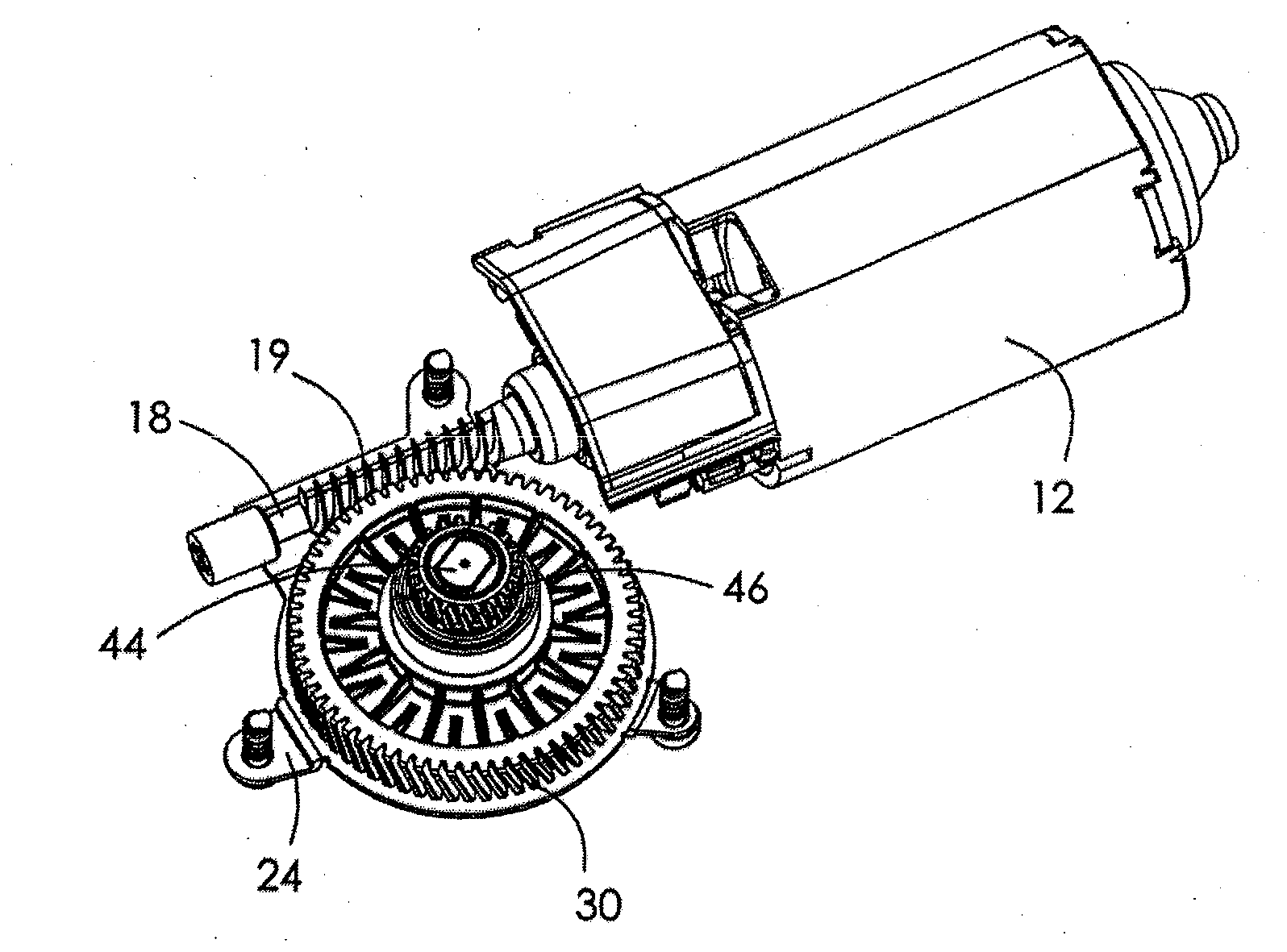
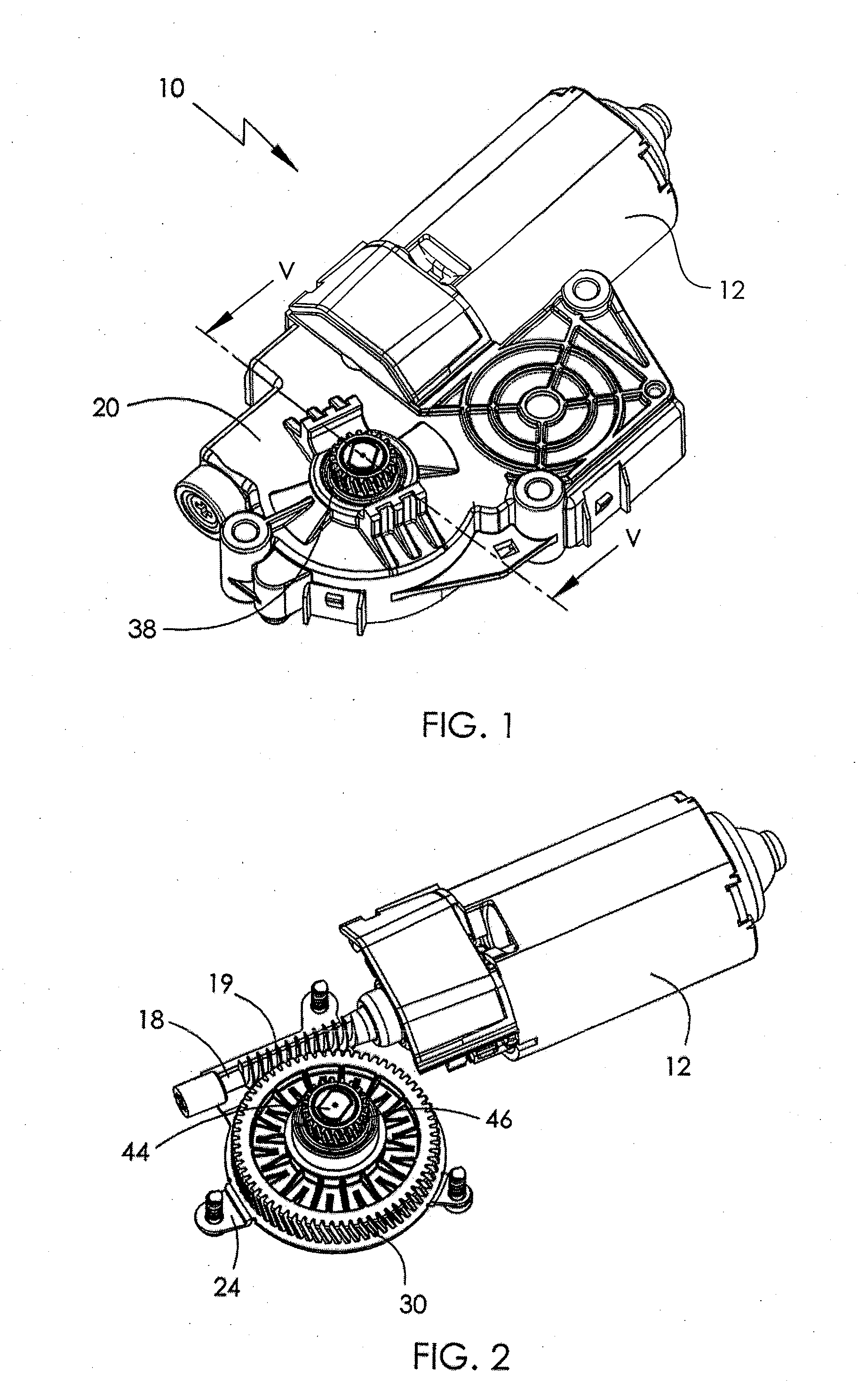
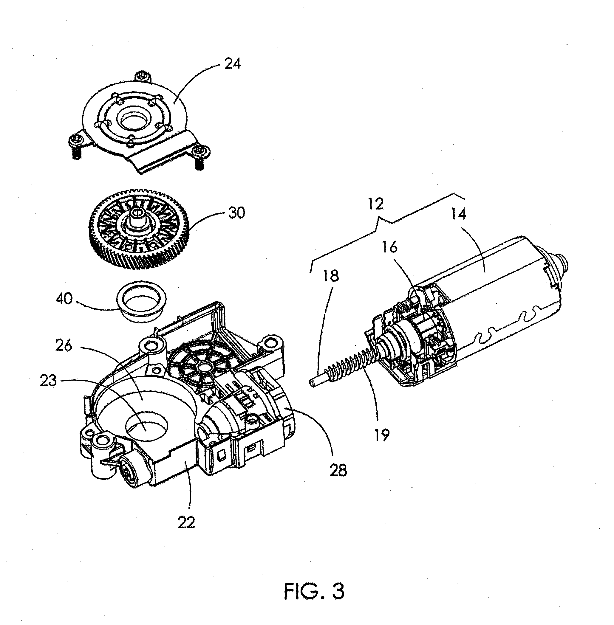
[0019]The Figs. show a gear motor assembly 10, according to the preferred embodiment of the present invention, which may be used to drive a sunroof of a vehicle. The gear motor assembly 10 includes a casing 20, a motor 12 fixed to the casing 20, a gear 30 housed in the casing 20 and driven by the motor 12, and a substantially tubular bearing 40 fixed to the casing 20 and in which a shaft portion 34 of the gear 30 is sleeved.

[0020]The casing 20 includes a base 22 and a cover 24. The base 22 includes a compartment 26, a connection part 28 for connecting the motor 12, and a through hole 23 formed at the center of a bottom plate of the compartment 26. The cover 24 defines a shaft hole 25 at the center thereof. The shaft hole 25 is coaxial with the through hole 23. The cover 24 can be connected to the base 22 by screws.

[0021]The motor 12 includes a stator 14 and a rotor 16 received in the stator 14. The rotor 16 includes a motor shaft 18. A worm 19 is formed on the motor shaft. The motor...


PUM


Abstract

A gear motor assembly includes a casing having a through hole, a motor fixed to the casing, an output shaft, a gear fixed to the output shaft and driven by the motor, and a substantially tubular bearing fixed in the through hole of the casing. The gear has a shaft portion that is sleeved in the bearing. A slot is formed in the inner surface of the bearing and/or the outer surface of the shaft portion and is filled with lubricant.

Description

CROSS REFERENCE TO RELATED APPLICATIONS[0001]This non-provisional patent application claims priority under 35 U.S.C. §119(a) from Patent Application No. 201110459370.8 filed in The People's Republic of China on Dec. 31, 2011.FIELD OF THE INVENTION[0002]The present invention relates to a gear motor assembly and in particular, to a gear motor assembly having a bearing surface with a groove for lubricant.BACKGROUND OF THE INVENTION[0003]A gear motor assembly for a sunroof usually includes a casing having a through hole, a motor fixed to the casing, a gear housed in the casing, and a bearing fixed in the hole. The gear has a shaft running through the hole and sleeved by the bearing. The shaft couples to the sunroof. During operation, the shaft rotates with respect to the bearing. In most gear motor assemblies, the inner wall of the bearing and the outer wall of the shaft are smooth arcuate surfaces. In order to reduce vibration or wobbling of the gear during rotation, the gap between th...

Claims


Application Information

Patent Timeline
Patent Type & Authority Applications(United States)
IPC IPC(8): F16H57/04
CPCF16H57/048F16H57/0498Y10T74/19991F16H57/0471F16C33/10Y10T74/19828Y10T74/1987B60J7/057H02K7/116F16H55/22F16H57/043
Inventor LAM, WING CHEUNGXU, QIANGMALABO, MARLOU TAMPUS
Owner JOHNSON ELECTRIC SA
Why Eureka
Try Eureka