Cable tie tensioning and cut-off tool

a cable tie and cutting tool technology, applied in the field of hand-held tensioning and cutting tools, can solve the problems of tool operator fatigue, weakening or breaking of the tie, stretching,

Active Publication Date: 2013-07-04
HELLERMANNTYTON CORP
View PDF5 Cites 9 Cited by
  • Summary
  • Abstract
  • Description
  • Claims
  • Application Information

AI Technical Summary

Benefits of technology

[0005]The present invention is directed to a hand-held tensionin

Problems solved by technology

One disadvantage of many presently available tie tensioning and severing tools is that those tools require an operator to apply an excessive force on their triggers which leads tool

Method used


Image

  • Cable tie tensioning and cut-off tool
  • Cable tie tensioning and cut-off tool
  • Cable tie tensioning and cut-off tool

Examples


Embodiment Construction

[0040]Although the disclosure hereof is detailed and exact to enable those skilled in the art to practice the invention, the physical embodiments herein disclosed merely exemplify the invention which may be embodied in other specific structures. While the preferred embodiment has been described, the details may be changed without departing from the invention.

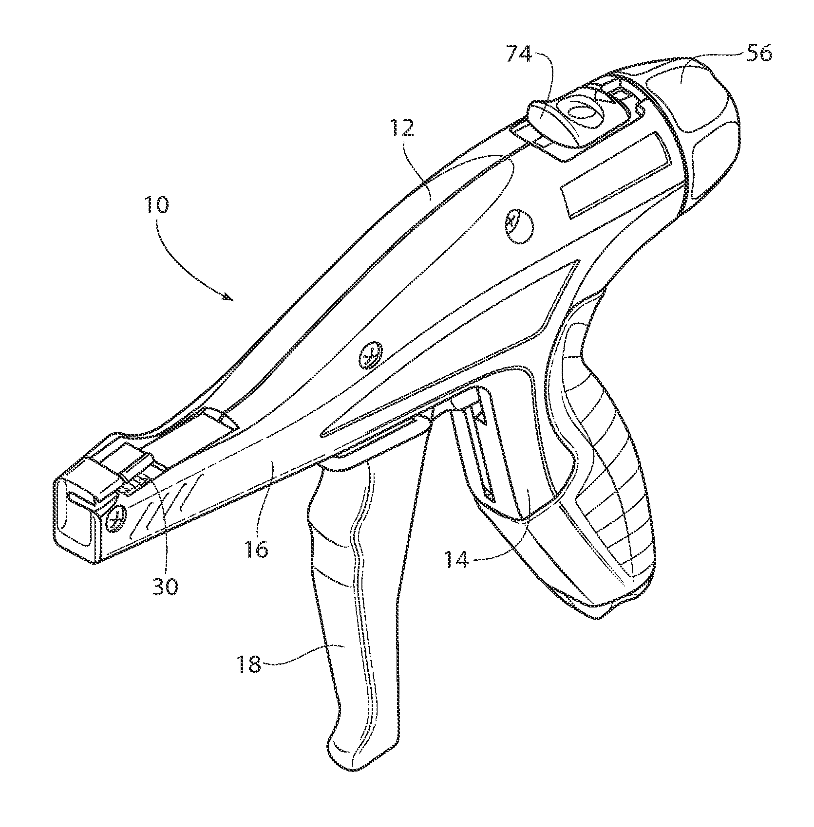
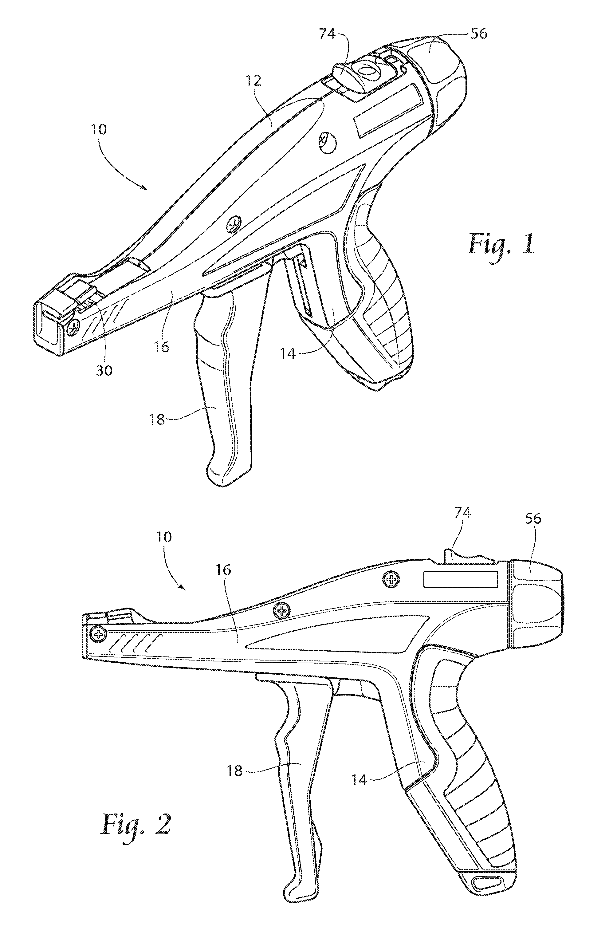
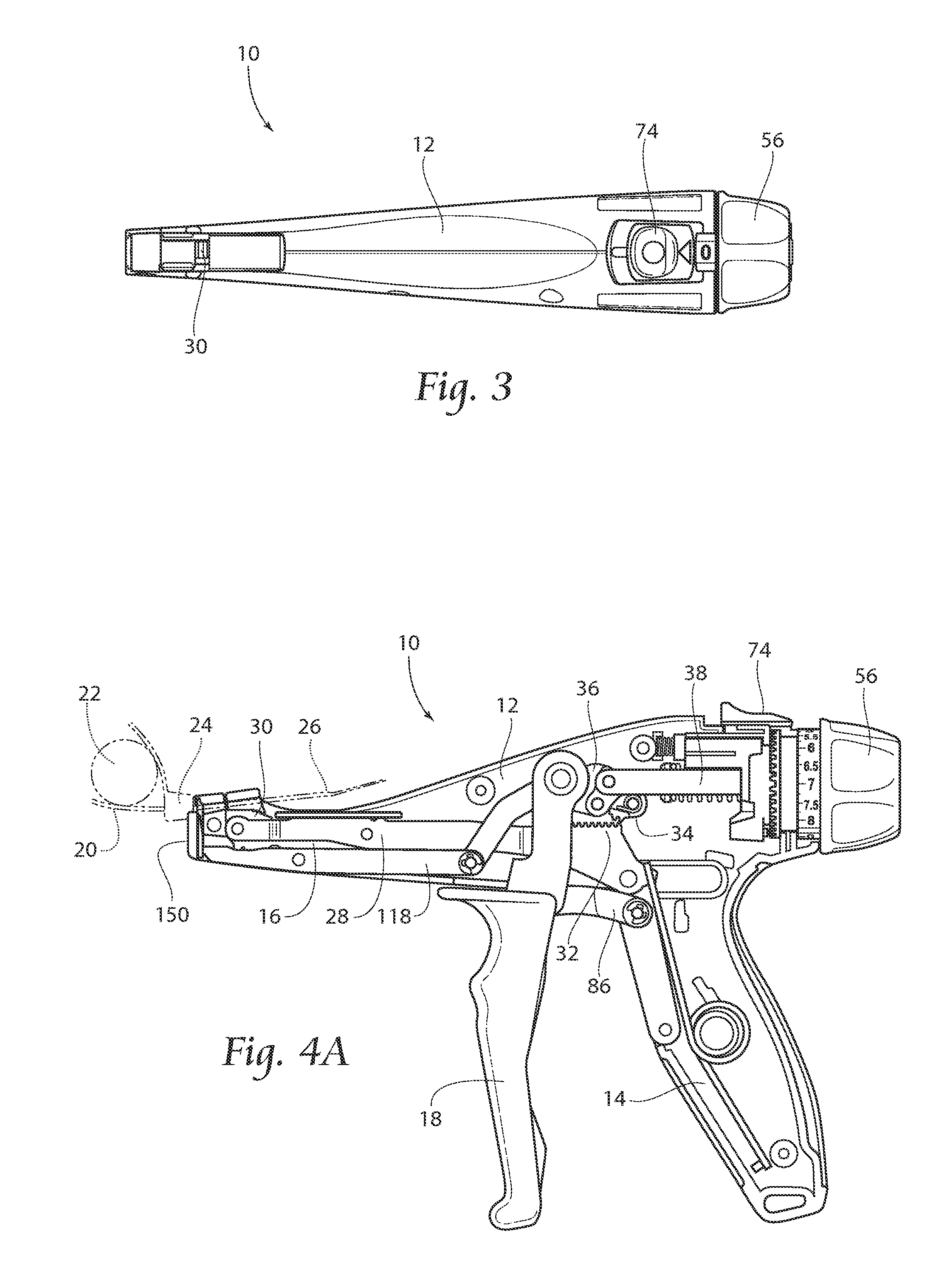
[0041]Referring now to the drawings and in particular to FIGS. 1 and 2, an embodiment of the cable tie tensioning and cut-off tool 10 incorporating the principles of the present invention is shown as having a housing 12 in the shape of a pistol or gun and having a handle or grip portion 14, a barrel portion 16, and a trigger 18. The trigger 18 is located forwardly of the grip 14 and under the barrel portion 16 where it fits naturally in the hand of a user (not shown). The tool 10 is typically used to install cable ties 20 (seen in phantom in FIGS. 4A-4D) around elongate bundles 22, such as wire cable or the like. As mentioned ea...


PUM

PropertyMeasurementUnit
Tensionaaaaaaaaaa
Resilienceaaaaaaaaaa

Abstract

A hand held tool for the tensioning and severing of cable ties, including reciprocating means for tensioning the cable tie tail, locking means to prevent further tensioning upon the attainment of a preselected tension level in the tie tail, and severing means to sever the tie tail from the cable tie head.

Description

RELATED APPLICATIONS[0001]This application claims the benefit of co-pending U.S. Provisional Patent Application Ser. No. 61 / 503,403 entitled “Cable Tie Tensioning and Cut-Off Tool and Method of Using”, filed 30 Jun. 2011.BACKGROUND OF THE INVENTION[0002]The present invention relates to hand held tensioning and cutting tools, and particularly to an improved hand tool for tensioning and cutting cable ties.[0003]Cable ties are widely used in a variety of environments and applications. They may be used, for example, to bundle a plurality of elongate wires, cables, or other elongate articles. Cable ties may also be used to secure elongate articles to rigid structures or used as hose clamps, by way of example. Such cable ties typically include an elongate tail portion which is threaded through an integral head portion to encircle the articles to be bound and the tie tail is drawn through the cable tie head to tightly bind the elongate articles into a bundle. After the tie is tensioned aro...

Claims


Application Information

Patent Timeline
IPC IPC(8): B26D7/08
CPCB26D7/08B65B13/027B25B25/00B26D7/14Y10T83/323
Inventor DYER, EDWARD P.
Owner HELLERMANNTYTON CORP
Why Eureka
Try Eureka