Hydraulic piston pump with a variable displacement throttle mechanism

Active Publication Date: 2013-07-04
HUSCO INT INC
View PDF3 Cites 8 Cited by
  • Summary
  • Abstract
  • Description
  • Claims
  • Application Information

AI Technical Summary

Benefits of technology

[0013]A throttle plate communicates with each of the plurality of inlet passages for varying a rate of fluid flow through the inlet passages. In one embodiment, the throttle plate extends across each of the plurality of inlet passages and has a plurality of control apertures there through. The throttle plate is moveable to alter alignment of the control apertures with the inlet passages and thereby vary a cross sectional area through which fluid flows in the inlet passages. This provides a variable orifice in each inlet passage.
[0014]One aspect of the present pump is that the flow area of the variable orifice is directly related to the magnitude of the fluid flow there through. Broadly speaking, as the throttle plate is moved from a position corresponding with the variable orifice bei

Problems solved by technology

A drawback of this type of pump is that during a dead portion of the piston cycle, between bottom dead center point and when the inlet becomes closed, no pumping action occurs.
This inactive time and initial short sealing length results in a sizeable inefficiency.
In addition this type of pump requires

Method used


Image

  • Hydraulic piston pump with a variable displacement throttle mechanism
  • Hydraulic piston pump with a variable displacement throttle mechanism
  • Hydraulic piston pump with a variable displacement throttle mechanism

Examples


Embodiment Construction

[0023]The term “directly connected” as used herein means that the associated components are connected together by a conduit without any intervening element, such as a valve, an orifice or other device, which restricts or controls the flow of fluid beyond the inherent restriction of any conduit. References herein to directional relationships and movement, such as top and bottom or left and right, refer to the relationship and movement of the components in the orientation illustrated in the drawings, which may not be the orientation of the components as attached to machinery.

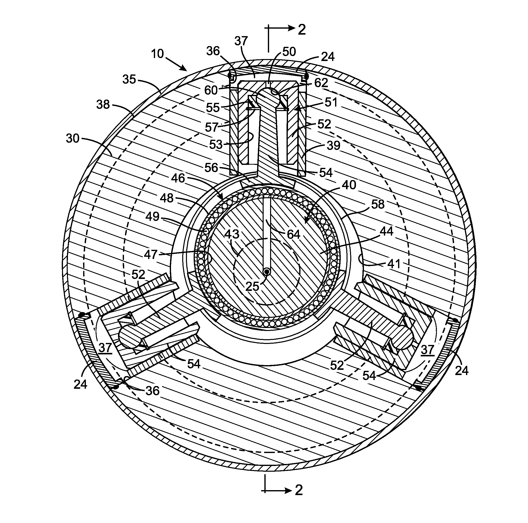
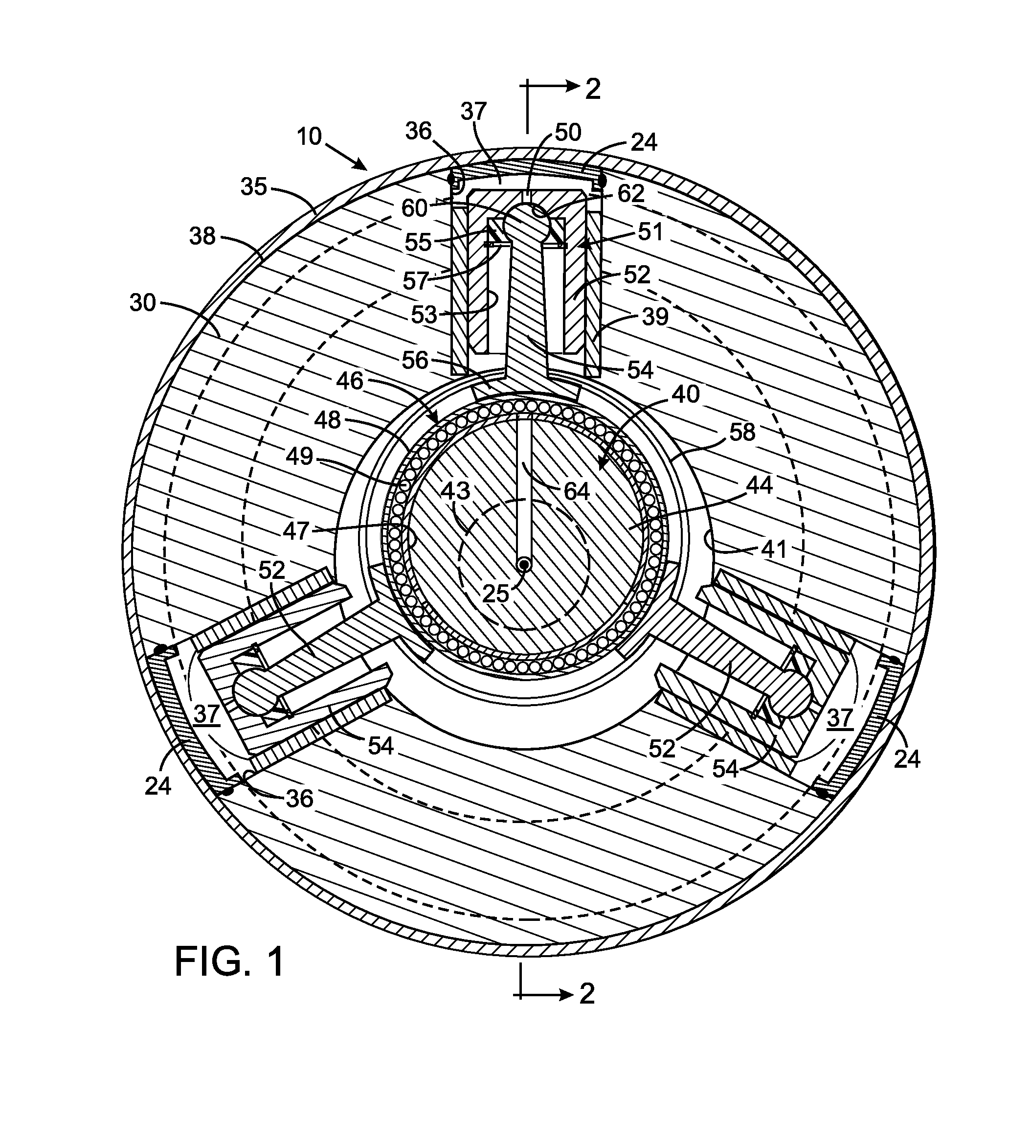
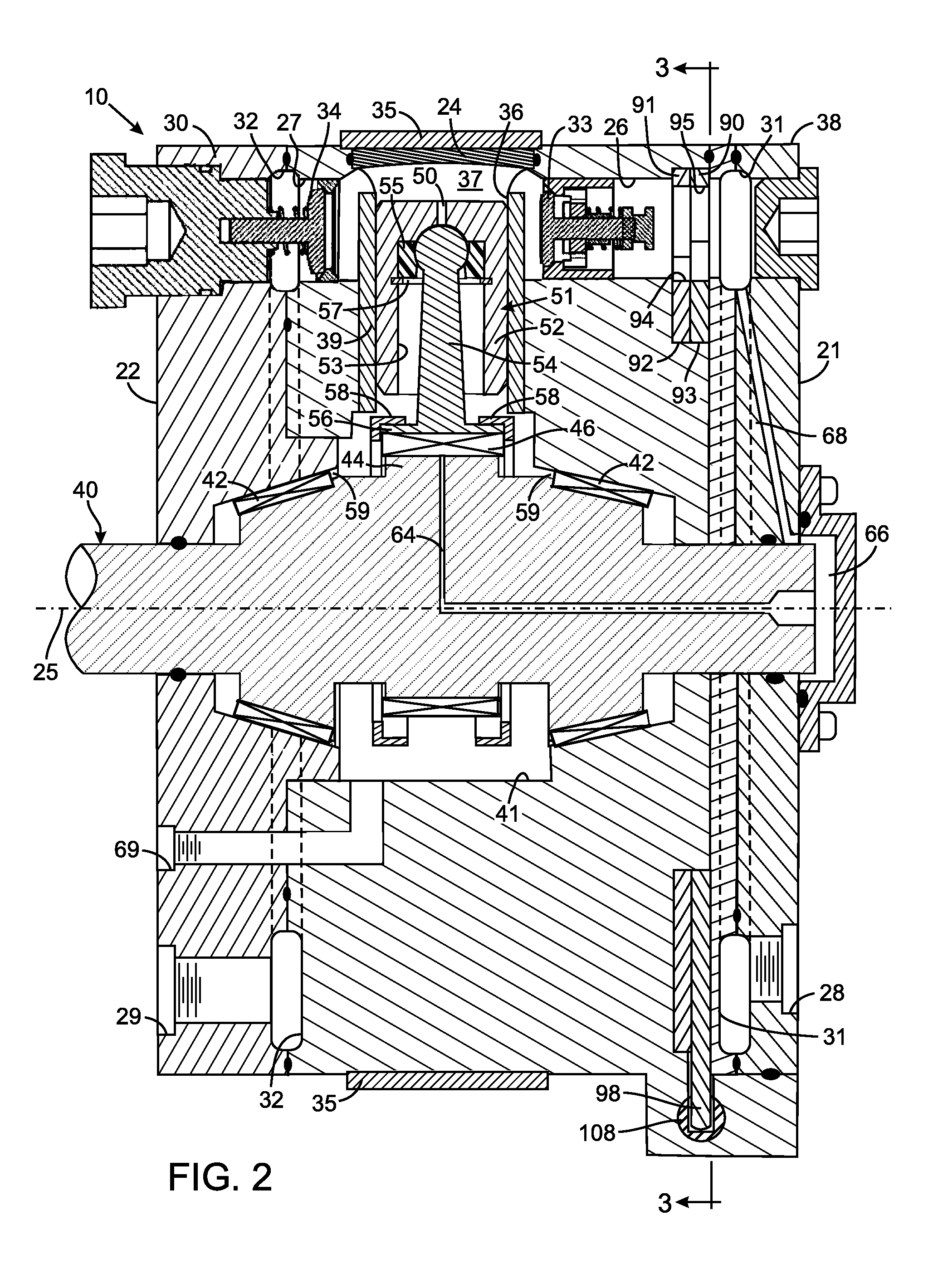
[0024]With reference to FIGS. 1 and 2, a hydraulic pump 10 has a cylinder block 30 with exterior first and second end surfaces 21 and 22 between which a cylindrical exterior side surface 38 extends. The cylinder block 30 has an inlet port 28 and an outlet port 29 through which hydraulic fluid is received and expelled from a hydraulic system. The inlet and outlet ports 28 and 29 open into inlet and outlet galleries...


PUM


Abstract

A radial piston pump has a plurality of cylinders within which pistons reciprocally move. Each cylinder is connected to a first port by an inlet passage that has an inlet check valve, and is connected to a second port by an outlet passage that has an outlet check valve. A throttling plate extends across the inlet passages and has a separate aperture associated with each inlet passage. Rotation of the throttling plate varies the degree of alignment of each aperture with the associated inlet passage, thereby forming variable orifices for altering displacement of the pump. Uniquely shaped apertures specifically affect the rate at which the variable orifices close with throttle plate movement, so that the closure rate decreases with increased closure of the variable orifices.

Description

CROSS-REFERENCE TO RELATED APPLICATIONS[0001]Not ApplicableSTATEMENT REGARDING FEDERALLY SPONSORED RESEARCH OR DEVELOPMENT[0002]Not ApplicableBACKGROUND OF THE INVENTION[0003]1. Field of the Invention[0004]The present invention relates to hydraulic pumps, such as those that have pistons that move radially against an eccentric shaft, and more particularly to mechanisms for controlling the flow of fluid through the cylinders in which the pistons move.[0005]2. Description of the Related Art[0006]A common type of radial piston pump comprises a body with a plurality of cylinders radially disposed around a drive shaft that is rotated by an external motor or engine. A separate piston is slideably received within each cylinder, thereby defining a chamber at the interior of the cylinder. The drive shaft has an eccentric cam and the pistons are biased by springs to ride against that cam. As the cam rotates, the pistons slide reciprocally within the respective cylinders, thereby reducing and e...

Claims


Application Information

Patent Timeline
IPC IPC(8): F04B49/22
CPCF04B1/0408F04B1/0421F04B53/16F04B49/22F04B1/0426Y10T137/85986
Inventor RAJPUT, PRASHANT K.STEPHENSON, DWIGHT
Owner HUSCO INT INC
Why Eureka
Try Eureka