[0007]In light of the foregoing background, the present invention provides a cavity assembly that includes at least one alignment assembly for aligning respective electro-optic components of an electro-optic
system. In this regard, the alignment assemblies align the electro-optic components and hold the electro-optic components in a manner that does not allow for undesirable free rotating motion, as compared to traditional
gimbal assemblies. Additionally, the present invention provides an electro-optic
system that includes a cavity assembly and has a housing that serves to protect the cavity assembly from the external environment and to conduct heat away from the cavity assembly. As such, the cavity assembly does not require a separate
heat sink and, thus, utilizes fewer components than conventional cavity assemblies. Associated methods for packaging the electro-optic
system and the cavity assembly are also provided.
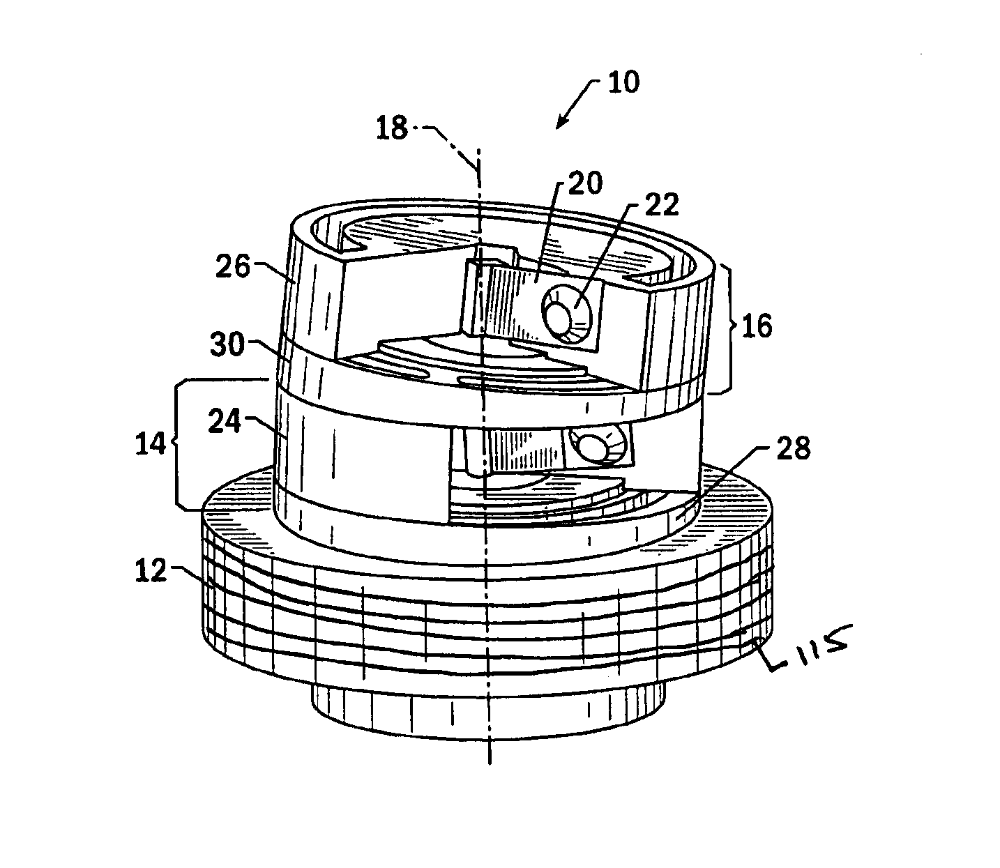
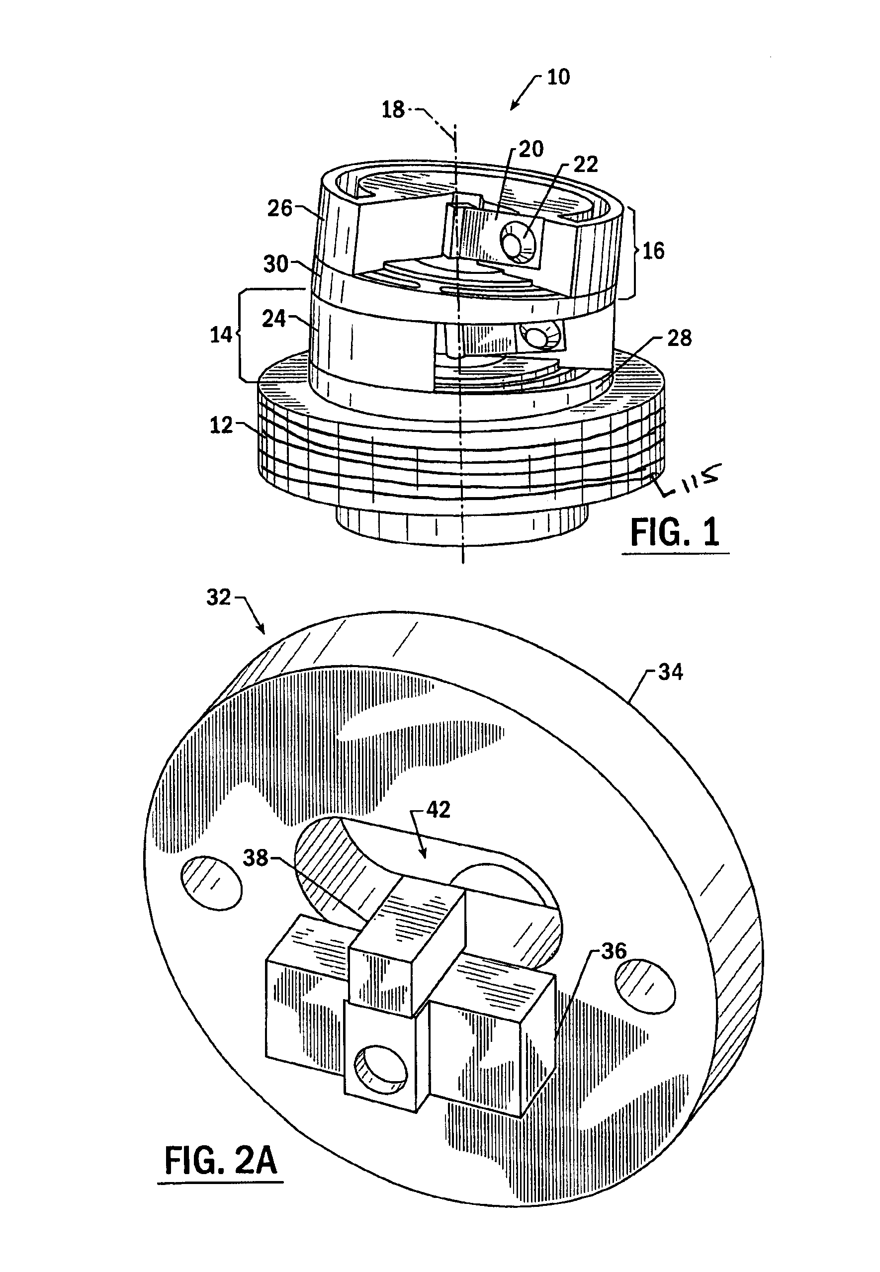
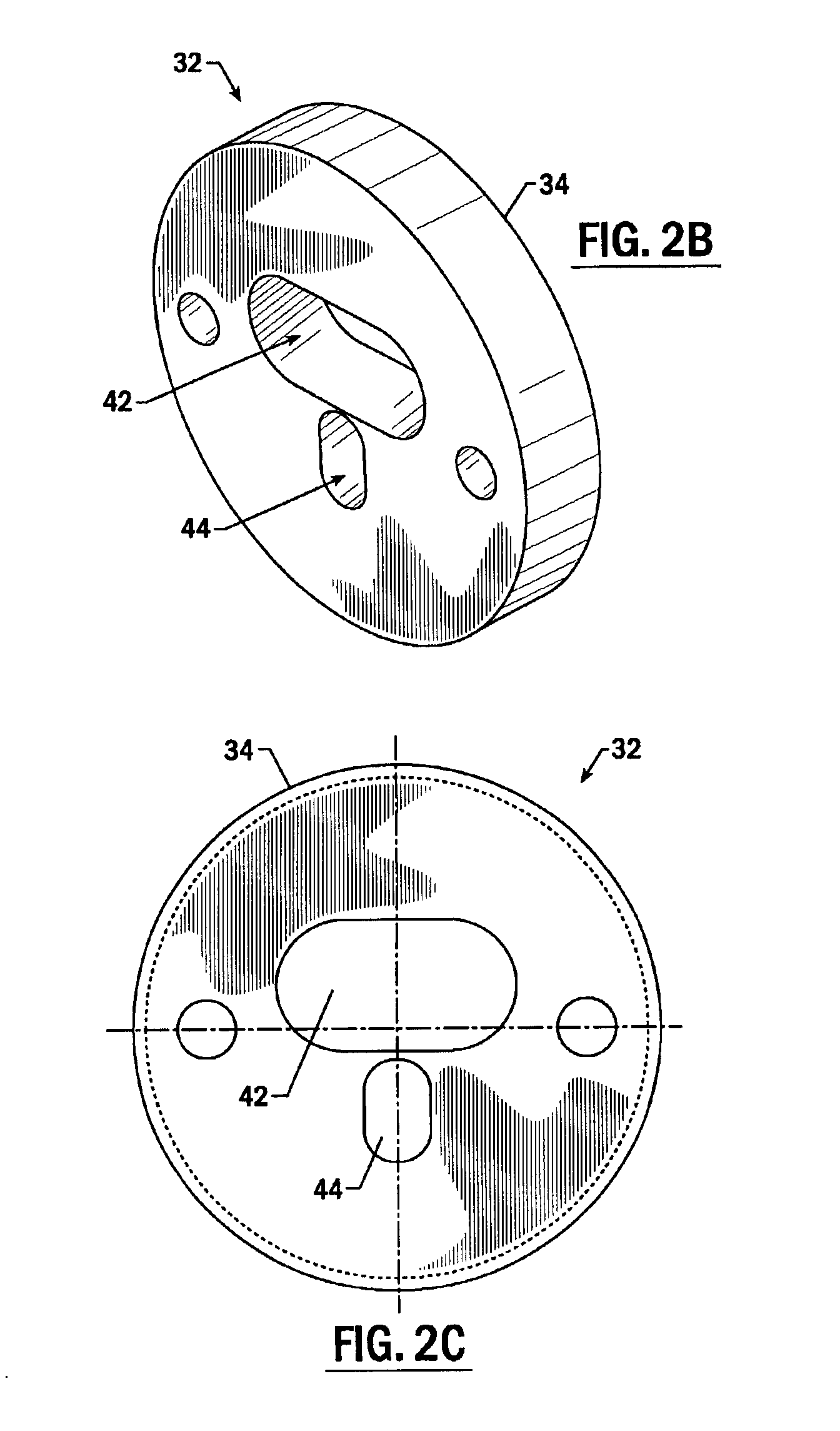
[0011]In one advantageous embodiment, the present invention provides a method of packaging a cavity assembly. The method generally begins by providing the mounting member and thereafter mounting the active gain medium to the mounting member. In embodiments including the support assembly, the active gain medium is mounted to the support assembly, and the support assembly is mounted within an aperture defined by the mounting member. Next, the alignment assemblies are positioned relative to the mounting member, where each alignment assembly includes an electro-optical component. The alignment assemblies are positioned by providing relative rotation between the alignment assemblies and the active gain medium to thereby alter the alignment of the respective electro-optic components with respect to the active gain medium. Then, at least one alignment assembly is secured to the mounting member.
[0013]According to another aspect of the present invention, an electro-optic system is provided. According to this aspect, the electro-optic system comprises a housing that is made of a thermally conductive material and defines an
internal cavity. The housing can additionally comprise a plurality of ribs. The system includes a pump assembly and a cavity assembly. The pump assembly, in turn, includes a pump source and is mounted at least partially within the
internal cavity of the housing. The cavity assembly comprises an active gain medium and at least one alignment assembly, which includes at least one electro-optic component. The alignment assemblies are disposed relative to the active gain medium such that the electro-optic components are at least partially aligned with the active gain medium. Additionally, the cavity assembly is disposed within the
internal cavity of the housing such that the cavity assembly is in
thermal contact with the housing to thereby permit
heat transfer from the active gain medium. To at least partially protect the cavity assembly from degradation, the internal cavity of the housing can be is isolated from an external environment.
[0014]According to yet another aspect of the present invention, a method of packaging an electro-optic system is provided. The method generally begins by providing the housing. The pump assembly, including a pump source, is then mounted at least partially within the internal cavity of the housing. Next, the cavity assembly is secured within the internal cavity defined by the housing. In this regard, securing the cavity assembly within the internal cavity includes establishing
thermal contact between the cavity assembly and the housing to thereby permit
heat transfer from the active gain medium to the housing. Then, the internal cavity is closed to thereby isolate the internal cavity from the external environment so as to at least partially protect the cavity assembly from degradation. In embodiments where the alignment assembly includes the mounting member, before securing the cavity assembly within the internal cavity, the active gain medium is fixed in position with respect to the mounting member. The alignment assemblies are then rotated relative to the mounting member to thereby alter the alignment of the respective electro-optic components with respect to the active gain medium. Next, the alignment assemblies are secured to the mounting member. Also, the mounting member of the cavity assembly can be secured within the internal cavity defined by the housing, such as by threadably securing the mounting member.
[0015]Therefore, the present invention provides a cavity assembly that includes at least one alignment assembly for aligning respective electro-optic components of an electro-optic system, and for holding the electro-optic components in a manner that does not allow for undesirable free rotating motion. Additionally, the present invention provides an electro-optic system that includes the cavity assembly and has a housing that serves to protect the cavity assembly from the external environment and to conduct heat away from the cavity assembly, thus not requiring an independent
heat sink.

