

Heat-dissipating device
- Summary
- Abstract
- Description
- Claims
- Application Information
AI Technical Summary
Benefits of technology
Problems solved by technology
Method used
Image

Examples
Embodiment Construction
[0034]The above objectives and structural and functional features of the present invention will be described in more detail with reference to preferred embodiment thereof shown in the accompanying drawings
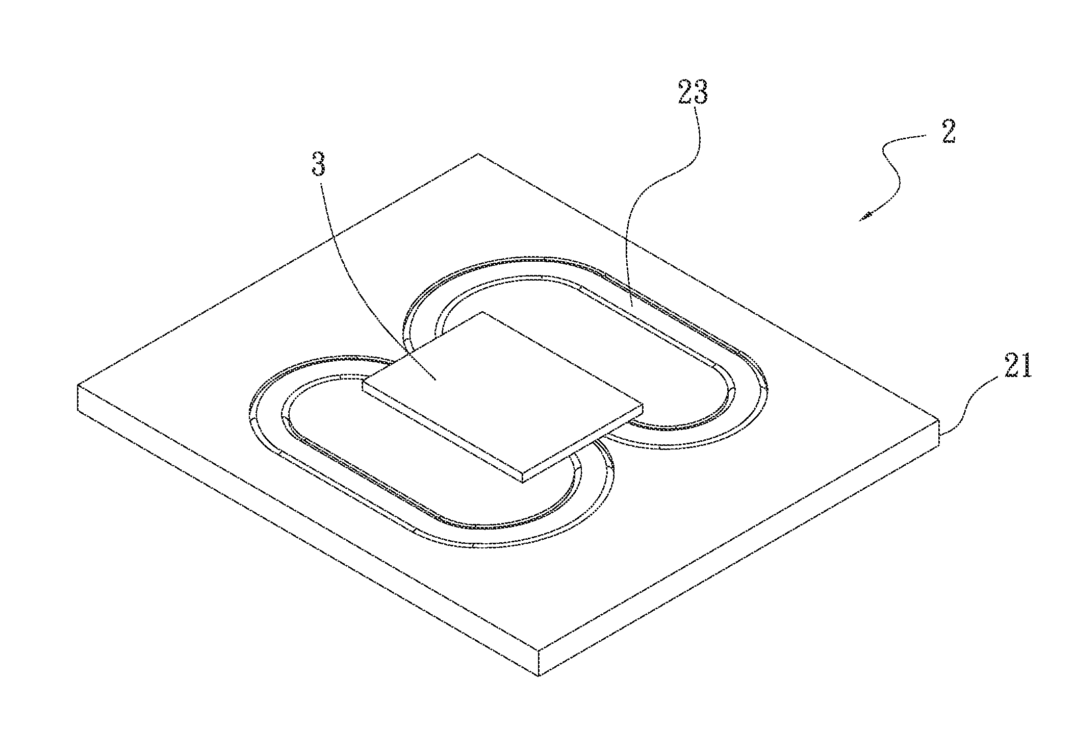
[0035]The present invention is directed to a heat-dissipating device. Please refer to FIGS. 2 and 3.
[0036]FIG. 2 is an assembled perspective view showing the first preferred embodiment of the present invention, and FIG. 3 is an exploded perspective view showing the first preferred embodiment of the present invention. The heat-dissipating device 2 includes a base 21 and a heat pipe 23. The base 21 has an accommodating trough 210. The accommodating trough 210 is provided on one side of the base 21 with a shape corresponding to that of the heat pipe 23. The way of providing the heat pipe 23 in the accommodating trough 210 is achieved by any one of tight-fitting, welding, wedging and gluing.
[0037]The heat pipe 23 is received in the accommodating trough 210. The heat pipe 23 has a first...
PUM
 Abstract
Description
Claims
Application Information