Hot-water supply system

a technology of hot water supply and salt water, which is applied in the field of hot water supply system, can solve the problems of reducing regeneration capacity, ion exchange resin gradually deteriorating, and ion exchange resin rapidly deteriorating, and achieves the effect of simple operation of supplying salt water in the regeneration treatment process

Inactive Publication Date: 2013-07-04
RINNAI CORP
View PDF8 Cites 3 Cited by
  • Summary
  • Abstract
  • Description
  • Claims
  • Application Information

AI Technical Summary

Benefits of technology

[0041]According to Embodiment 2, the switching to the water supplying and the operat

Problems solved by technology

However, if the regeneration treatment is repeated, since the salt is consumed and becomes deficient, it is necessary to appropriately replenish salt.
However, the ion exchange resin is gradually deteriorated by repeating the regeneration treatment, and if the ion exchange resin is significantly deteriorated, it is necessary to exchange the ion exchange resin.
However, if the regeneration treatment is not appropriately performed and the ion exchange resin is used in a state where the water softening capacity is decreased, the ion exchange resin is rapidly deteriorated, the regeneration capacity is decreased in a short time, and thus, it is necessary to exchange the ion exchange resin early.
However, if t

Method used


Image

  • Hot-water supply system
  • Hot-water supply system
  • Hot-water supply system

Examples


example 1

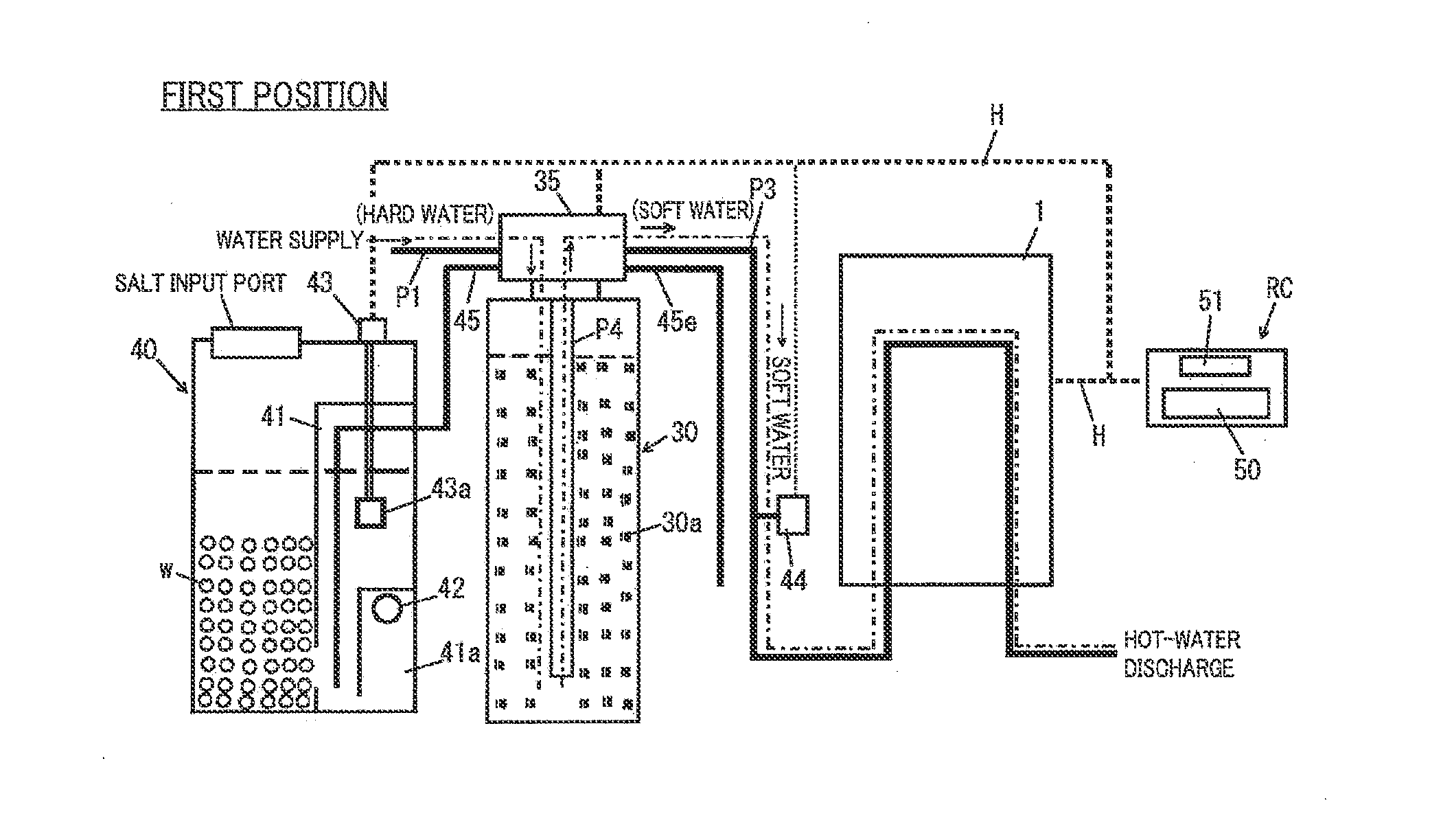
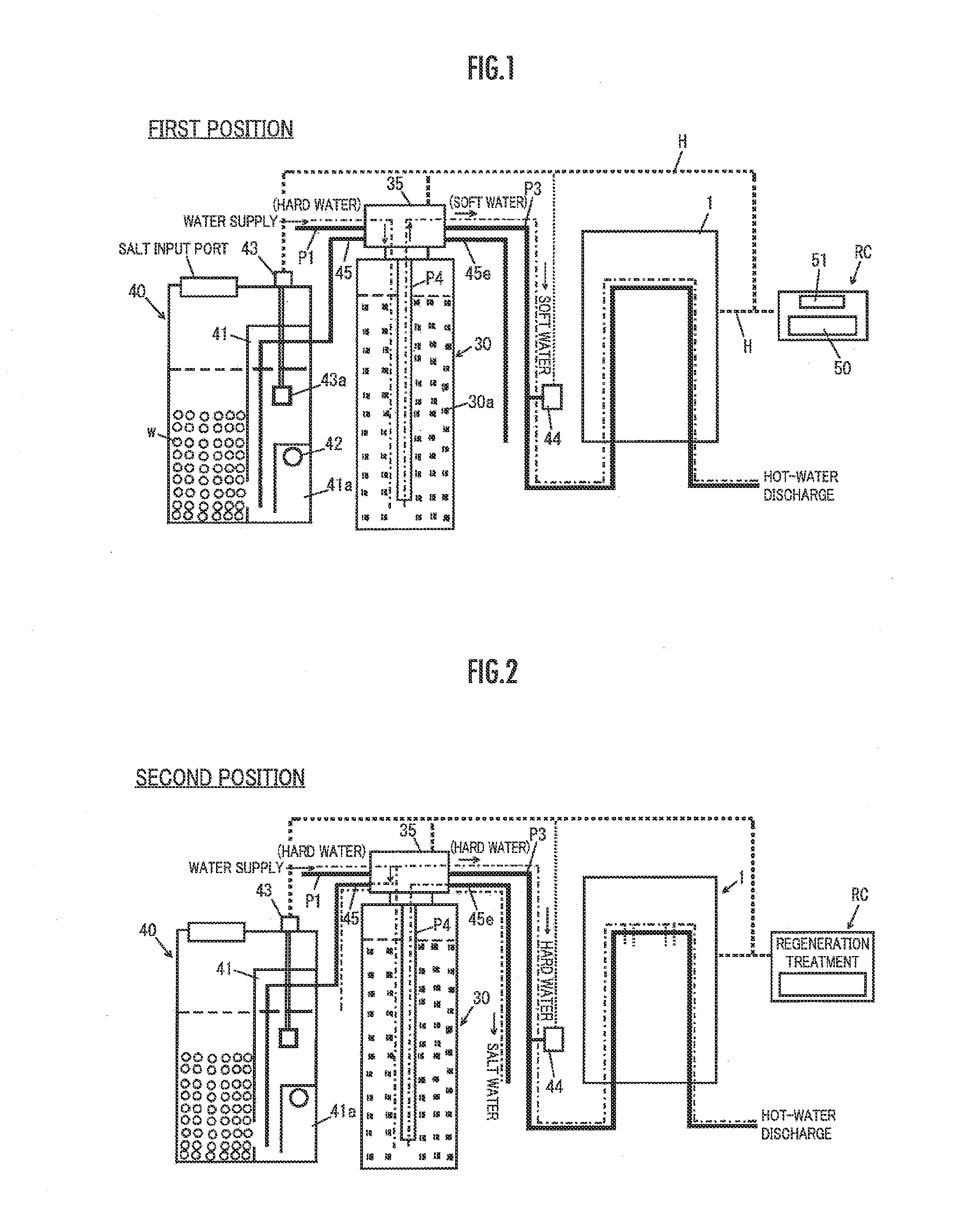
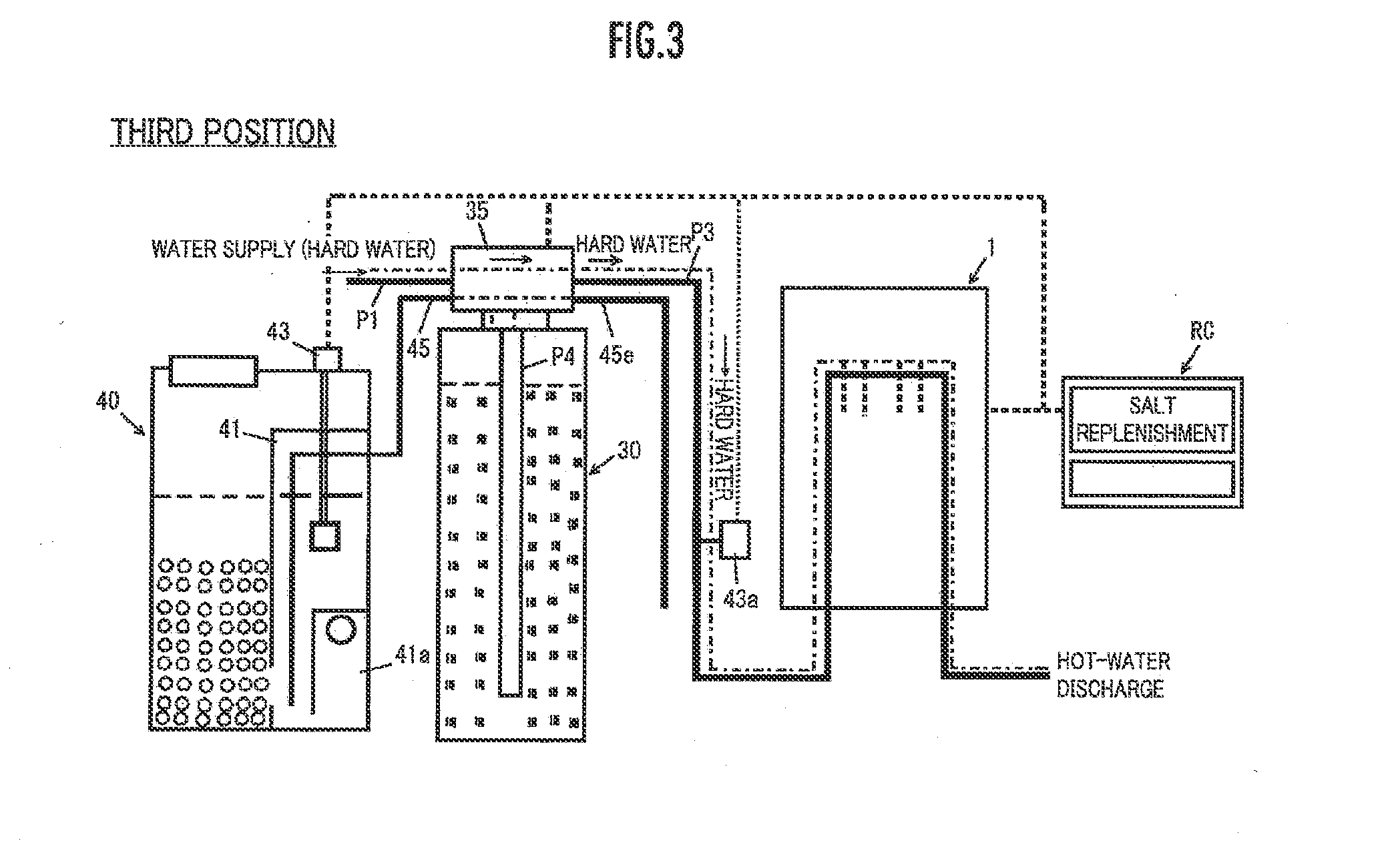
[0052]Example 1 includes a hot-water supply device 1, a water softening device 30, and a regeneration salt water supply device 40, and a switching valve 35 is disposed on the water softening device 30.

[0053]The regeneration salt water supply device 40 includes a divided chamber 41, a water level detection chamber 41a is provided in the divided chamber, and a water level detection unit 42 is provided in the water level detection chamber 41a. A lower end of a salt water suction pipe 45 reaches a bottom portion of the divided chamber 41, and an upper end of the salt water suction pipe 45 is connected to a third inlet 35c of the switching valve 35. The third inlet 35c selectively communicates with a first passage (a passage which communicates with a first outlet 35d) 36a of the switching valve 35.

[0054]The basic configuration of the switching valve 35 is as follows (FIG. 4).

[0055]The number of the inlets of the switching valve 35 is three, and the number of the outlets is three. Moreove...

example 2

[0102]Next, Example 2 will be described.

[0103]In Example 2, the determination of the timing of the regeneration treatment, the determination of the timing of the salt replenishment, and the determination of the service life of the ion exchange resin are performed by a simple method based on empirical rules. Since the method has a premise in that the regeneration treatment and the salt replenishment are performed in a predetermined manner (a predetermined salt is replenished by a predetermined amount, or the like), if the regeneration treatment and the salt replenishment are not performed in a predetermined manner, the service life of the ion exchange resin is damaged. However, the salt replenishment is demanded due to the display on the remote controller, the display is continued until the salt is replenished, and thus, it is considerably expected that the salt is immediately replenished. Moreover, since the water softening device is bypassed until the salt is replenished and the ho...


PUM

PropertyMeasurementUnit
Flow rateaaaaaaaaaa
Frequencyaaaaaaaaaa

Abstract

A hot-water supply system includes a switching valve (35) which has a bypass circuit which bypasses the water softening device (30) by directly connecting the water supply pipe (P1) and the inlet pipe (P3) of a hot-water supply device to each other, and a control unit (50). The control unit (50) includes a switching valve drive circuit which switches the switching valve (35) to the mode in which water is supplied from the water supply pipe (P1) to the hot-water supply device (1) via the bypass circuit, based on the determination of the timing of salt replenishment, and a display drive circuit which displays intention, in which salt replenishment is needed, on a display portion (51) of a remote controller (RC).

Description

TECHNICAL FIELD[0001]The present invention relates to a hot-water supply system which includes a water softening device, and particularly, to a hot-water supply system which maintains a predetermined water softening capacity by regenerating an ion exchange resin of a water softening device and recovering the water softening capacity (or ion exchange capacity) repeatedly.BACKGROUND ART[0002]In a hot-water supply system which includes a water softening device, there are various combinations of a hot-water supply device, a water softening device, and a regeneration device (specifically, a regeneration salt water supply device), and for example, an example of Patent Document 1 is as illustrated in FIG. 7.[0003]In the hot-water supply system, a hot-water supply device 1 and a water softening device 2 are connected to each other by a data communication line 3, a remote controller 4 is connected to the data communication line 3, and the remote controller 4 controls the hot-water supply dev...

Claims


Application Information

Patent Timeline
IPC IPC(8): C02F1/42
CPCC02F1/008C02F1/42F24D19/0092C02F2209/05C02F2209/055C02F2303/22F24D17/00B01J49/0086B01J49/0095C02F2209/005C02F2209/006C02F2303/16B01J49/75B01J49/85
Inventor OGAI, FUMIO
Owner RINNAI CORP
Why Eureka
Try Eureka