
Three-dimensional image generating device

Inactive Publication Date: 2013-07-04
ALTEK CORP
View PDF3 Cites 5 Cited by
  • Summary
  • Abstract
  • Description
  • Claims
  • Application Information

AI Technical Summary

Benefits of technology

The invention is about a device that generates 3D images. It uses two processing units to process left-eye and right-eye images separately and then combines them into a 3D image. This eliminates the need for a high-capacity buffer memory, making it cost-effective and efficient. The resulting 3D image has a higher integration rate.

Problems solved by technology

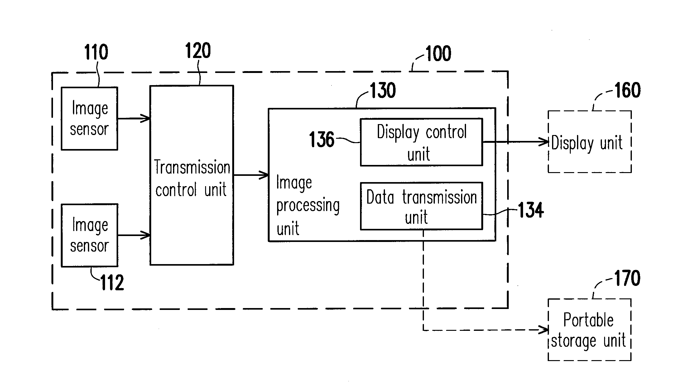
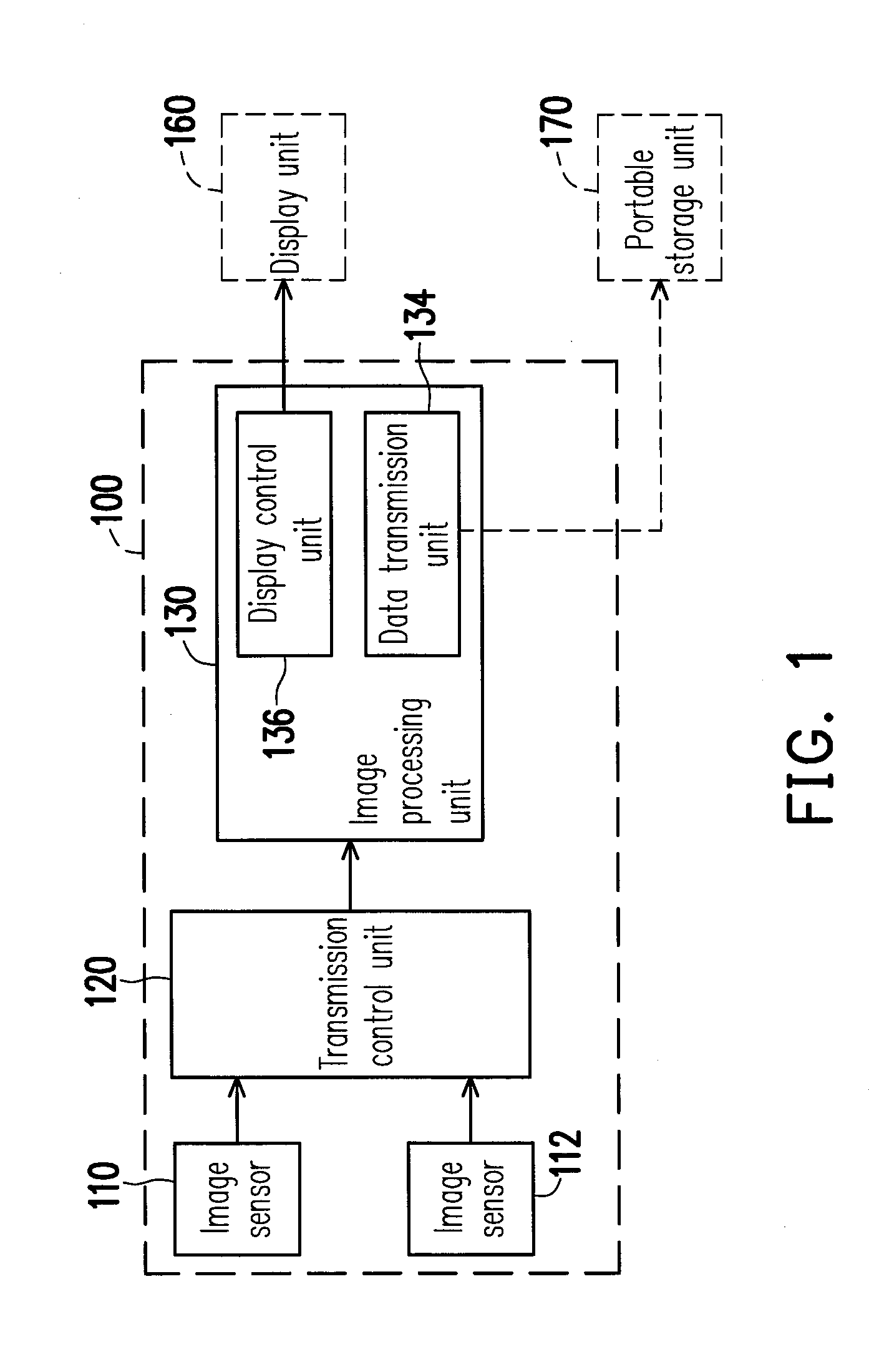
Besides, the transmission control unit 120 requires a different design in image transmission sequence therefore is difficult to implement.
As to a high-resolution image system, because a large memory is required inside the chip, the cost is very high and accordingly the technique described above is not applicable.
On the other hand, because the 3D image integration operation is performed by an overall control section in the stereoscopic camera, a lot of image processing time is wasted on memory access and the processing process is slowed down.
Thereby, through the two techniques described above, 3D image live view cannot be accomplished and a large buffer memory has to be adopted unnecessarily.

Method used


Image

  • Three-dimensional image generating device
  • Three-dimensional image generating device
  • Three-dimensional image generating device

Examples


first embodiment

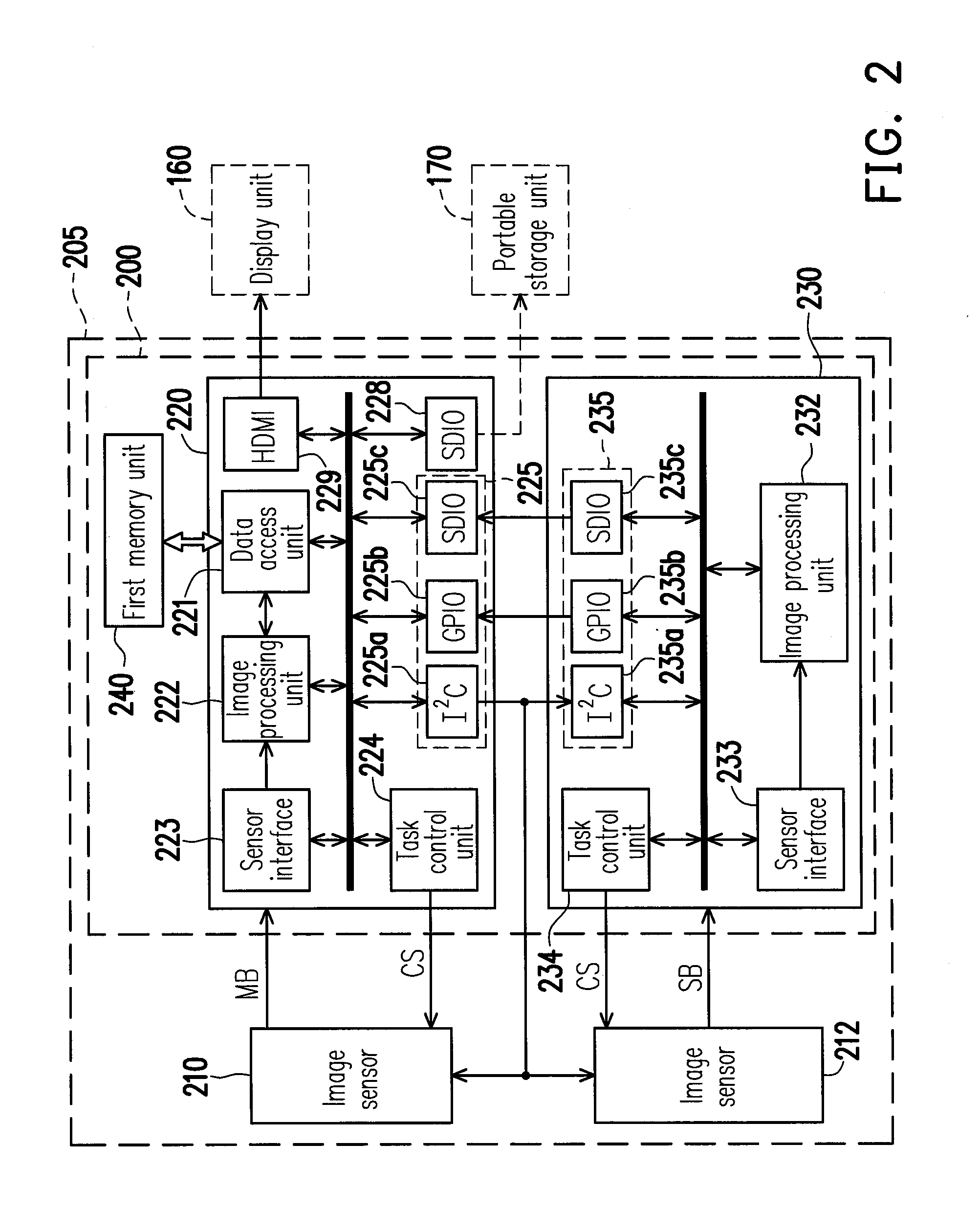
[0029]FIG. 2 is a function block diagram of a three-dimensional (3D) image generating device 200 and a 3D image capturing apparatus 205 using the same according to the first embodiment of the invention. The 3D image capturing apparatus 205 has two image sensors 210 and 212 and the 3D image generating device 200. The 3D image capturing apparatus 205 may be a digital camera, a video camera, or any other apparatus which can capture 3D images. However, the type of the 3D image capturing apparatus 205 in the present embodiment is not limited to foregoing examples.

[0030]The image sensors 210 and 212 in the present embodiment are implemented with CMOS image sensors (CIS) or charge couple device (CCD) image sensors. The first image sensor 210 is coupled to a first (master) processor 220 of the 3D image generating device 200 through an image bus MB. The first image sensor 210 captures a two-dimensional (2D) to-be-processed image representing a first human eye (for example, a right eye) and o...

second embodiment

[0053]FIG. 5 is a function block diagram of a 3D image generating device 500 and a 3D image capturing apparatus 505 using the same according to the second embodiment of the invention. The second embodiment is similar to the first embodiment, and the difference between the two is that the 3D image generating device 500 further includes a second memory unit 540 and the second (slave) processor 230 further includes a second data access unit 521. The first data access unit 221 is coupled to the first memory unit 240 and configured to access the first memory unit 240. Similarly, the second data access unit 521 is coupled to the second memory unit 540 and configured to access the second memory unit 540. The second task control unit 234 also issues commands to the second data access unit 521 to coordinate and execute operations of the second (slave) processor 230.

[0054]Thereby, the 3D image generating device 500 can process 3D images having larger file sizes by using the two image processi...

third embodiment

[0066]FIG. 7 is a function block diagram of a 3D image generating device 700 and a 3D image capturing apparatus 705 using the same according to the third embodiment of the invention. The third embodiment is similar to the first and the second embodiment described above, and the difference between the third embodiment and foregoing two embodiments is that the first (master) processor 220 and the second (slave) processor 230 in the 3D image generating device 700 respectively include a first data access unit 721 and a second data access unit 731. The first data access unit 721 and the second data access unit 731 are both coupled to the first memory unit 740 respectively through a first access bus and a second access bus. Namely, the first memory unit 740 is a dual port memory unit, and which includes at least a first access bus (coupled to the first data access unit 721) and a second access bus (coupled to the second data access unit 731) so that it can be accessed by two processors at...


PUM


Abstract

A three-dimensional (3D) image generating device including a first memory unit, a first (master) processor, and a second (slave) processor is provided. The first processor and the second processor respectively include a first image processing unit and a second image processing unit. The first processor further includes a data access unit. The first image processing unit and the second image processing unit respectively receive images representing a first human eye and a second human eye and generate a first image and a second image through image processing. The data access unit receives the first image from the first image processing unit and writes it into the first memory unit according to a predetermined 3D image format. The second image processed by the second image processing unit is transmitted to the data access unit and written into the first memory unit according to the predetermined 3D image format.

Description

CROSS-REFERENCE TO RELATED APPLICATION[0001]This application claims the priority benefit of Taiwan application serial no. 100149265, filed Dec. 28, 2011. The entirety of the above-mentioned patent application is hereby incorporated by reference herein and made a part of this specification.BACKGROUND OF THE INVENTION[0002]1. Field of the Invention[0003]The invention generally relates to an image processing technique, and more particularly, to a three-dimensional (3D) image generating device.[0004]2. Description of Related Art[0005]Along with the development of technologies and image capturing techniques, many manufacturers have been devoted to the research and development of stereoscopic image capturing techniques in order to allow people to capture stereoscopic video images by themselves. FIG. 1 is a block diagram of a conventional three-dimensional (3D) digital camera 100. The digital camera 100 respectively captures a left-eye two-dimensional (2D) image and a right-eye 2D image by...

Claims


Application Information

Patent Timeline
IPC IPC(8): H04N13/02G06K9/00H04N13/239H04N13/30
CPCH04N13/04H04N13/0296H04N13/0239H04N13/30H04N13/296H04N13/239
Inventor PAN, CHIA-HOLIAW, MING-JIUNCHEN, SHUEI-LIN
Owner ALTEK CORP
Learn More