Method for rapid imaging of biologic fluid samples

a technology for biologic fluids and imaging methods, applied in the field of rapid imaging of biologic fluid samples, can solve the problems of high resolution imaging speed, labor-intensive techniques, and inapplicability to commercial laboratory applications, and achieve the effects of reducing the cost of high-resolution imaging

Inactive Publication Date: 2013-07-04
ABBOTT POINT CARE
View PDF8 Cites 31 Cited by
  • Summary
  • Abstract
  • Description
  • Claims
  • Application Information

AI Technical Summary

Benefits of technology

[0007]According to an aspect of the present invention, a method for analyzing a biologic fluid sample is provided. The method includes the steps of: a) disposing the biologic fluid sample within a chamber adapted to quiescently hold the biologic fluid sample; b) imaging the biologic fluid sample at a first resolution, and producing first image signals representative of a low resolution image of the sample; c) analyzing the first image signals to identify one or more first characteristics of the sample, and determining a position of each first characteristic within the chamber using a map of the chamber; d) imaging a portion of the biologic fluid sample at a second resolution and producing second image signals representative of a high resolution image of the sample, which portion of the biologic fluid sample is determined using the one or more first characteristics and the map, and wherein the second resolution is greater than the first resolution; and e) analyzing the biologic fluid sample using the second image signals.
[0008]According to another aspect of the present invention, an apparatus for analyzing a biologic fluid sample quiescently disposed within an analysis chamber is provided. The apparatus includes an objective lens assembly, at least one image dissector, and a processor. The objective lens assembly is operable to image the biologic fluid sample at a first resolution and a second resolution, which second resolution is greater than the first resolution. The processor is adapted to: a) analyze first image signals produced by the image dissector with the objective lens at the first resolution; b) identify one or more first characteristics of the sample; c) determine a position of each first characteristic within the chamber using a map of the chamber; d) create an image of a portion of the biologic fluid sample at the second resolution and to produce second image signals representative thereof, which portion of the biologic fluid sample is determined using the one or more first characteristics and the map; and e) analyze the biologic fluid sample using the second image signals.
[0009]According to another aspect of the present invention, a method for imaging a biologic fluid sample is provided. The method includes the steps of: a) disposing the biologic fluid sample within a chamber adapted to quiescently hold the biologic fluid sample, which sample fills an area within the chamber; b) mapping the chamber, which map defines a plurality of grid squares, each grid square having an area; and c) imaging portions of the biologic fluid sample, each image portion aligned with a different grid square of the map, and each image portion having an area, and which image portions together form a collective image of the sample residing within the chamber, and wherein the collective area of the image portions has an area that is less than the area filled by the sample residing within the chamber.

Problems solved by technology

These techniques are also labor-intensive and thus not practically feasible for commercial laboratory applications.
Nonetheless, the speed at which automated devices operate can be significantly limited by high resolution imaging.

Method used


Image

  • Method for rapid imaging of biologic fluid samples
  • Method for rapid imaging of biologic fluid samples
  • Method for rapid imaging of biologic fluid samples

Examples


Embodiment Construction

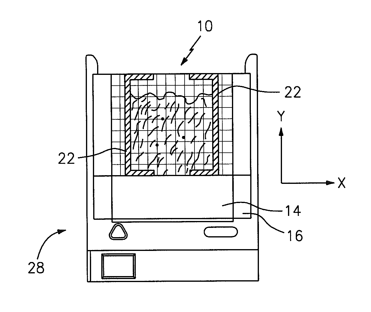
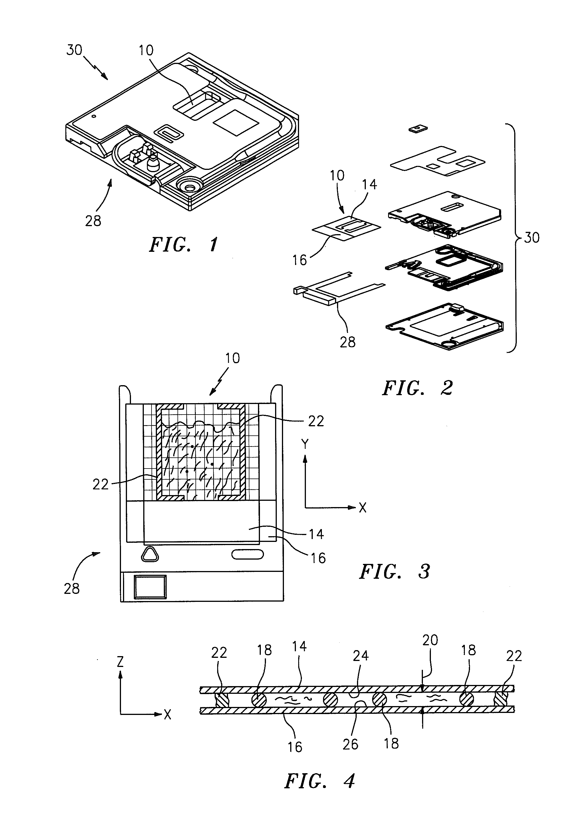
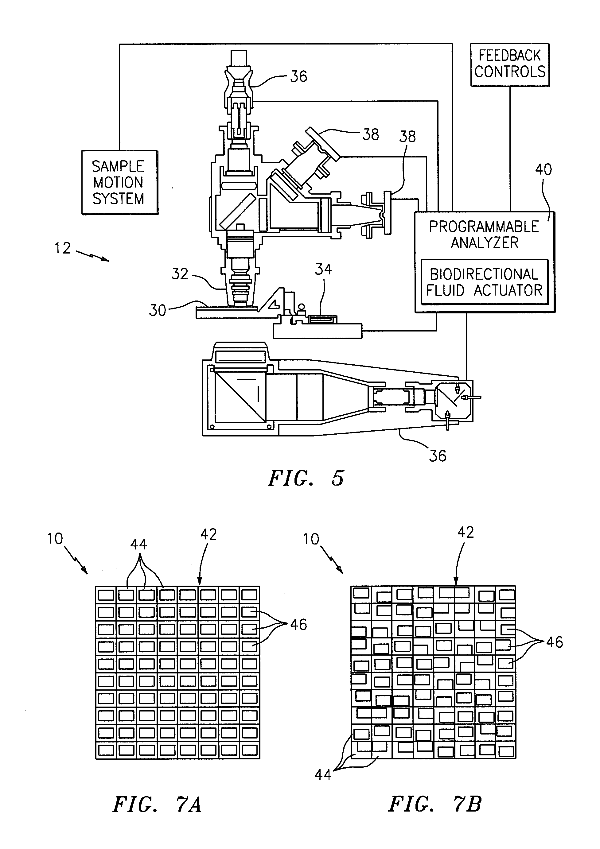
[0019]Referring to FIGS. 1 and 5, the present invention includes a method and an apparatus for analyzing a biological fluid sample (e.g., whole blood) quiescently residing within an analysis chamber, which analysis chamber 10 is configured to permit automated analysis of the sample by an analysis device 12. The sample quiescently residing within the chamber 10 is imaged, and the image of the sample is analyzed using the analysis device 12.

[0020]An illustration of a chamber 10 that can be used with the present invention is shown in FIGS. 1-4. The chamber 10 is formed by a first planar member 14, a second planar member 16, and typically has at least three separators 18 disposed between the planar members 14,16. At least one of the planar members 14,16 is transparent. The height 20 of the chamber 10 is typically such that sample residing within the chamber 10 will travel laterally within the chamber 10 via capillary forces. FIG. 4 shows a cross-section of the chamber 10, including the ...


PUM

PropertyMeasurementUnit
volume capacityaaaaaaaaaa
lengthaaaaaaaaaa
widthaaaaaaaaaa

Abstract

A method for analyzing a biologic fluid sample is provided. The method includes the steps of: a) disposing the biologic fluid sample within a chamber; b) imaging the biologic fluid sample at a first resolution, and producing first image signals representative of a low resolution image of the sample; c) analyzing the first image signals to identify one or more first characteristics of the sample, and determining a position of each first characteristic within the chamber using a map of the chamber; d) imaging a portion of the biologic fluid sample at a second resolution and producing second image signals, which portion of the sample is determined using the first characteristics and the map, and wherein the second resolution is greater than the first resolution; and e) analyzing the biologic fluid sample using the second image signals.

Description

[0001]The present application is entitled to the benefit of and incorporates by reference essential subject matter disclosed in the following U.S. Provisional Patent Applications: Ser. Nos. 61 / 581,851, filed Dec. 30, 2011; and 61 / 594,136, filed Feb. 2, 2012.BACKGROUND OF THE INVENTION[0002]1. Technical Field[0003]The present invention generally relates to methods for imaging a biologic fluid sample, and more specifically relates to methods and apparatuses for imaging a biologic fluid sample at more than one resolution and in some instances less than the entire sample.[0004]2. Background Information[0005]Historically, biologic fluid samples such as whole blood, urine, cerebrospinal fluid, body cavity fluids, etc., have had their particulate or cellular contents evaluated by smearing a small undiluted amount of the fluid on a slide and evaluating that smear under a manually operated microscope. Reasonable results are attainable using these techniques, but they rely heavily upon the te...

Claims


Application Information

Patent Timeline
Patent Type & Authority Applications(United States)
IPC IPC(8): G01N33/49
CPCB01L3/5027G01N2015/1486G01N15/1475G01N33/49B01L2400/0406B01L9/52B01L2200/0689B01L2300/0822B01L3/508B01L9/56
Inventor XIE, MIN A.HERZOG, DAVIDVERRANT, JOHN
Owner ABBOTT POINT CARE
Why Eureka
Try Eureka