Projection device and projection-type video display device

a projection device and video display technology, applied in the direction of instruments, holographic light sources/light beam properties, holographic processes, etc., can solve the problems of large optical system, low light intensity, and relatively short lifecycle of high intensity discharge lamps such as high pressure mercury lamps. to achieve the effect of minimizing an optical system

Active Publication Date: 2013-07-04
DAI NIPPON PRINTING CO LTD
View PDF1 Cites 14 Cited by
  • Summary
  • Abstract
  • Description
  • Claims
  • Application Information

AI Technical Summary

Benefits of technology

[0078]According to the present invention, it is possible to display a plurality of videos, to allow speckles to be inconspicuous, and to miniaturize an optical system.

Problems solved by technology

In the illumination device of the related art, since the light beam is spread, there is a loss in light intensity, and there is a problem in that an optical system becomes large.
Further, high intensity discharge lamp such as a high pressure mercury lamp has a relatively short lifecycle, and in the case where the lamp is used for an optical type projector or the like, the lamp needs to be frequently replaced.
In addition, since a relatively large optical system such as a dichiroic mirror is needed in order to extract the light beams of the primary color components, there is a problem in that the size of the whole apparatus is increased as described above.
Further, since the diameter of the light beam of the laser can be easily controlled, a loss of light may not easily occur.
On the other hand, in the type using the coherent light source such as a laser source, there is another problem in that speckles occur.
If the speckle occurs on the screen, it is observed as punctate luminance irregularity (brightness irregularity), so that it becomes a factor of exerting physiologically bad influence on the observer.
In the type of using the coherent light source, since there is an intrinsic problem in that the speckles occur, techniques for suppressing the occurrence of speckles have been proposed.

Method used


Image

  • Projection device and projection-type video display device
  • Projection device and projection-type video display device
  • Projection device and projection-type video display device

Examples


first basic embodiment

Configuration of First Basic Embodiment

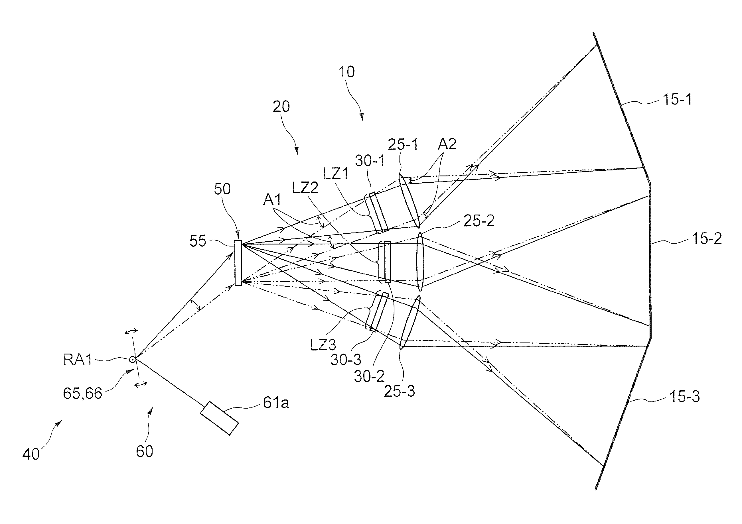
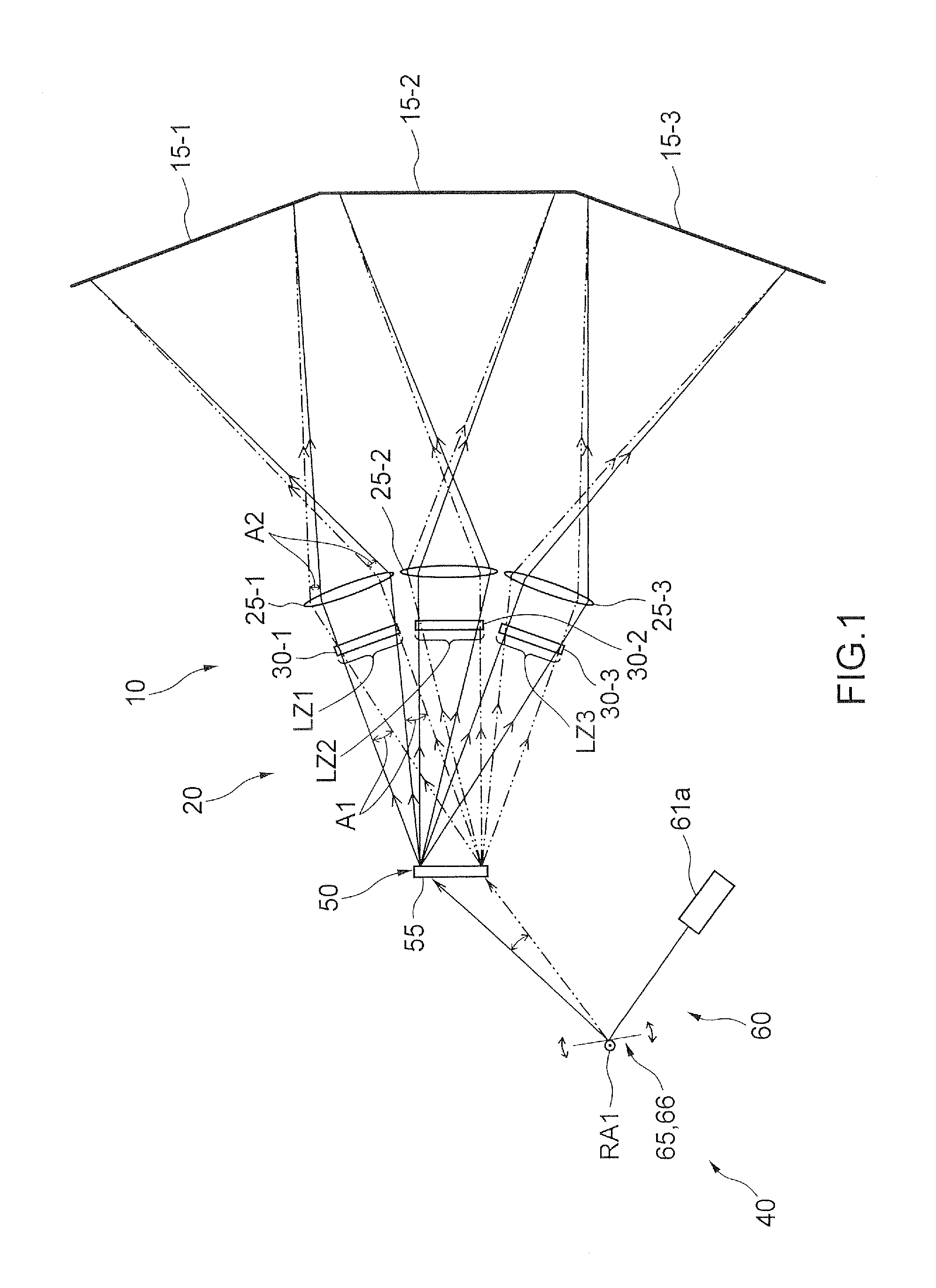
[0094]First, a configuration of a projection-type video display device which includes an illumination device and a projection device projecting coherent light beams and which is capable of allowing speckles to be inconspicuous to display a plurality of videos will be described mainly with reference to FIGS. 1 to 5.

[0095]The projection-type video display device 10 illustrated in FIG. 1 includes three screens 15-1, 15-2, and 15-3 and a projection device 20 which projects video images including coherent light beams. The projection device 20 includes an illumination device 40 which simultaneously illuminates three illuminated regions LZ1, LZ2, and LZ3 located on a virtual plane with the coherent light beams, three spatial light modulators 30-1, 30-2, and 30-3 which are disposed at positions overlapping the illuminated regions LZ1 to LZ3 and are illuminated with the coherent light beams by the illumination device 40, and three projection optical sys...

second basic embodiment

Configuration of Second Basic Embodiment

[0139]First, the configuration of the projection-type video display device will be described with reference to FIG. 6, and the description is made mainly on different components from the first basic embodiment.

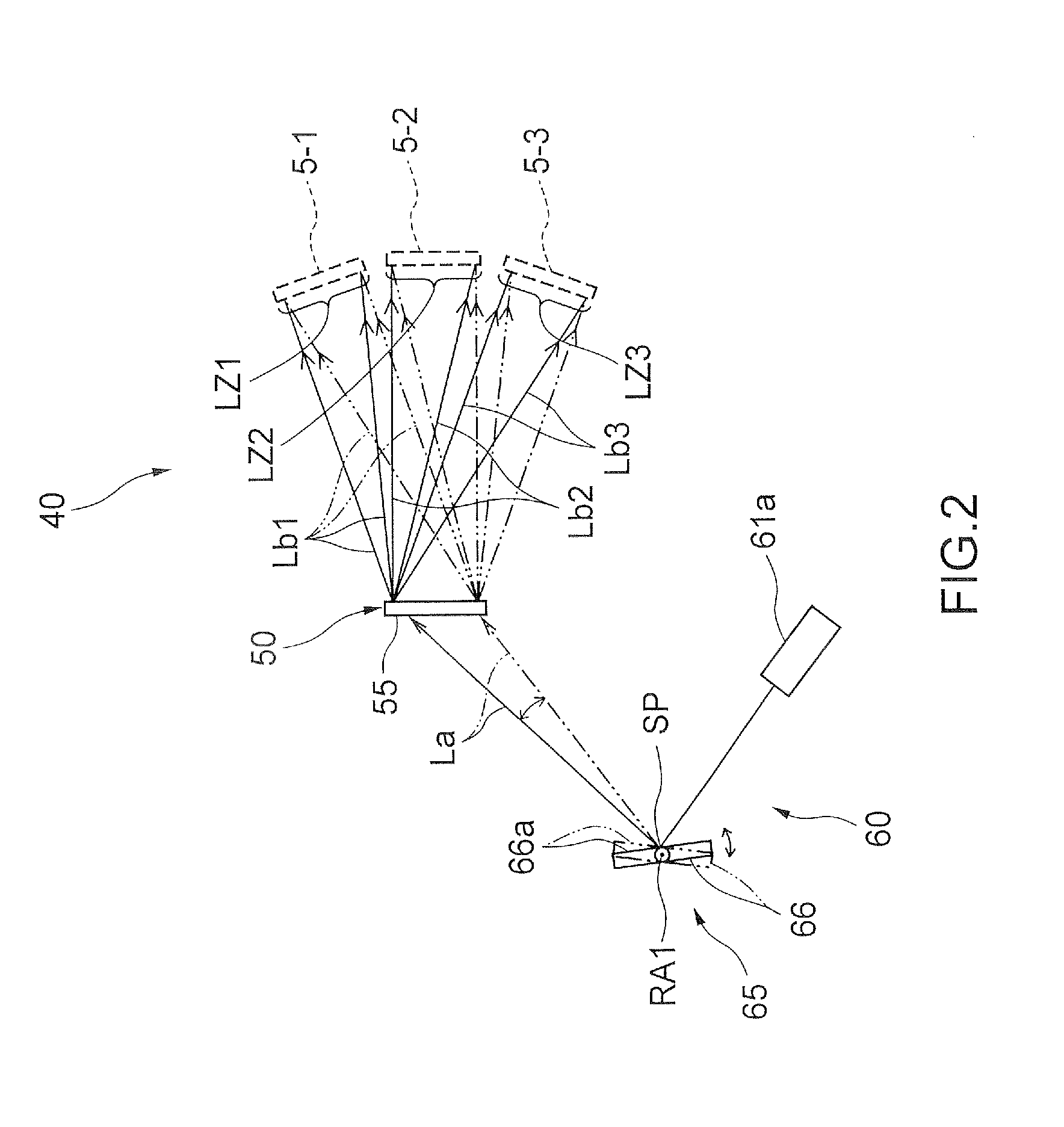
[0140]As illustrated in FIG. 6, the optical element 50 includes the hologram recording medium 55a which can reproduce the image of the scattering plate corresponding to each illuminated region on the illuminated regions LZ1 to LZ3. In addition, the hologram recording medium 55a includes three regions 55a-1, 55a-2, and 55a-3 corresponding to the images 5-1 to 5-3 of the scattering plates 6-1 to 6-3. In other words, on the hologram recording medium 55a, in the region 55a-1, the image 5-1 of the corresponding scattering plate 6-1 is recorded, in the region 55a-2, the image 5-2 of the corresponding scattering plate 6-2 is recorded, and in the region 55a-3, the image 5-3 of the corresponding scattering plate 6-3 is recorded. In the example il...

first modified example of second basic embodiment

[0164]In the second basic embodiment, the coherent light beam is allowed to scan the hologram recording medium 55a, so that any one of the illuminated regions LZ1 to LZ3 is illuminated one by one. On the contrary, as illustrated in FIG. 9, the three laser sources (light source units) 61a-1 to 61a-3 may be configured to be used to allow the coherent light beams to simultaneously scan the regions 55a-1 to 55a-3 of the hologram recording medium 55a, so that all the illuminated regions LZ1 to LZ3 can be simultaneously illuminated.

[0165]In the example illustrated in FIG. 9, the mirror device 66 receives the coherent light beams from the laser sources 61a-1 to 61a-3 roughly at the standard point SP. Therefore, the coherent light beams of which the propagation directions are finally adjusted by the mirror device 66 can be incident on the hologram recording medium 55a as the reproduction illumination light beams La1 to La3, each of which can constitute one light beam of the diverging flux f...


PUM


Abstract

A projection device includes an optical element including a hologram recording medium where information is multiplexedly recorded in each position so as to allow a coherent light beam to be diffused to a plurality of regions, an irradiation device configured to irradiate the optical element with the coherent light beam so as to allow the coherent light beam to scan the hologram recording medium, spatial light modulators configured to be illuminated with the coherent light beam which is incident from the irradiation device to the hologram recording medium to be diffused to the plurality of regions, and projection optical systems, each projection optical system projecting modulation image obtained on each spatial light modulator on corresponding screen. The coherent light beam, which is incident to each position of the hologram recording medium to be diffused, is illuminated on a plurality of the spatial light modulators.

Description

TECHNICAL FIELD[0001]The present invention relates to a projection device and a projection-type video display device displaying a plurality of videos by using a coherent light beam, and more particularly, to a projection device and a projection-type video display device capable of allowing occurrence of speckles to be inconspicuous.BACKGROUND ART[0002]A projection-type video display device, including a screen and a projection device which projects a video image on the screen, has been widely used. In a typical projection-type video display device, a two-dimensional image as a basic image is generated by using a spatial light modulator such as a liquid crystal micro display or a DMD (digital micromirror device), and the two-dimensional image is magnified and projected on a screen by using a projection optical system, so that a video is displayed on the screen.[0003]As the projection device, various types including a commercialized product called an “optical type projector” have been ...

Claims


Application Information

Patent Timeline
Patent Type & Authority Applications(United States)
IPC IPC(8): G02B27/48
CPCG02B5/32G02B26/101G02B27/48G03B21/2033G03H1/0005G03H1/22G03B21/208G03H1/32G03H2222/36H04N9/3129H04N9/3147G03H2225/60G03H1/2286G02B26/10G03B21/2013G03B21/2046
Inventor KURASHIGE, MAKIOISHIDA, KAZUTOSHITAKANOKURA, TOMOEOOYAGI, YASUYUKI
Owner DAI NIPPON PRINTING CO LTD
Why Eureka
Try Eureka